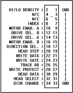

The connector on a floppy drive consists of 34 conductors. Both control and data use this same cable. Most cables have a twist that interchanges pins 10 through 16 at the end of the cable (on drive 1). Most floppy connectors have a "key" between pins 4 & 6, and 3 & 5, to prevent the cable from being reversed. At the other end, the dual row connector that attaches to the controller card will usually have a set of ridges that coincide with cutouts in the controller card's connector. Note that old style floppy-only controllers used a card-edge connector just like that of the drive. Figure TT4 illustrates the typical floppy connector (at the drive)
 fig. tt4
ST506/412 HARD DRIVES (MFM & RLL)
This standard drive system uses two cables; a 34 conductor control cable, and a 20 conductor data cable. The control cable contains a twist of the conductors going to the farthest drive, which is drive "C:" on most systems.
 fig. tt5
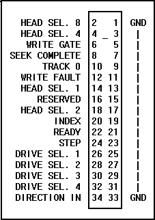
This twist consists of conductors 25 through 29. As with the floppy cable, the ST506/412 cables normally have a key to prevent reversal, and the controller end has a pin-type connector, while the drive end has a card-edge type connector. Figure TT5 illustrates an ST506/412 control cable connector and pinouts (at the drive).
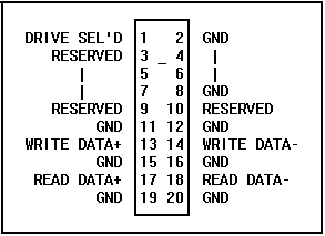
Though control signals for both hard drives go through a single 34 conductor cable, data flows through a separate 20 conductor cable for each drive (C,D). Figure TT6 illustrates an ST506/412 data cable connector (at the drive).
 fig. tt6