
In this section, you'll find all kinds of technical information that doesn't fit anywhere else in TheRef(tm). If you have some good stuff you'd like to share with others, please, by all means, send it along, and I'll try to fit it into the next version.
Floppy Drives normally use two cables. A 34-wire Control/Data cable, and a 4-wire Power cable. The Power connector is a Molex(tm) molded type, keyed to prevent accidents. The Control/Data connector, at the floppy controller was a card-edge type for the original IBM PC. Later Controllers adopted the dual-row pin type connector. The Control/Data connector at the floppy drive has remained a card-edge type for 5.25" drives, and a mixture of pin or card-edge types for 3.5" drives, with most now being produced with the pin type connector.
Although the original 5.25" floppy drives had jumpers for selection of drive number, IBM devised a way to eliminate it's workers having to change them on the assembly line. It did this by adding a twist in the 34-wire cable between wires 10 and 16 just before the connector for drive 1. This effectively changed the drive number setting on the floppy from 1 to 2, or from 2 to 1. Combined with the setting of each floppy to drive 2, it forced the drive at the end of the cable (drive 1 position) to change it's setting to 1. Now, any drive could be swapped without worry as to the drive number setting.
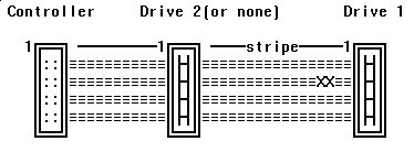
Figure TT1 illustrates a twisted type floppy cable. Wires 10-16 are twisted before the last (drive1) connector.
 fig. tt1
Hard Drives normally have three cables. A 34-wire Control cable, a 20-wire Data cable, and a 4-wire Power cable. The Power cable is essentially the same as that of the floppy drives. The Control cable normally employs much the same twist technique as in floppy drives, except that the drive number is carried in a different area of the cable. For hard drives, wires 25 through 29 are twisted. The Data cable employs a different technique. A separate Data cable is run for each hard drive attached.
So far, we've been talking about cabling for a class of hard drives referred to as the ST506/412 type, which includes MFM and RLL encoded drives. Another class, an improved ST506/412, referred to as ESDI, also inherited the same cabling scheme.
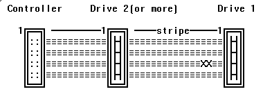
Figure TT2 illustrates a twisted ST506/412 type hard drive Control cable. Wires 25-29 are twisted before the last (drive 1) connector.
 fig. tt2
Figure TT3 illustrates an ST506/412 type Data cable (straight through).
 fig. tt3
IMPORTANT NOTE: Pin #1 on any drive cable SHOULD be indicated by a colored stripe. If you should find the stripe by connector pin 34 (or 20), inspect the whole cable VERY thoroughly!
DRIVE SELECT JUMPERS: For both Floppy and Hard drives, when the 34 pin cable has a twist, the device number should be set to the second position. Drives numbered 0-3, set to 1, those numbered 1-4, set to 2. When cables without a twist are used, Floppy "A", and(or) Hard drive "C" should be set to 1, and the second Floppy and (or) Hard drive should be set to 2.
TERMINATORS: When using more than one drive on a cable (ie; 2FDs or 2HDs), the terminating resistor pack should be left on the drive furthest from the controller, and removed from the drive closest to the controller.
NOTE: On SCSI drives, the Host Adapter also has resistors. These are needed to terminate both ends of the bus. Since the SCSI bus can have up to 7 devices attached to it, only the Host Adapter and the device farthest from it will retain the resistors. All devices in between should have theirs removed.