

SCSI Termination is really pretty simple once you understand what's going on. The whole scheme revolves around the statement that "The SCSI bus must be terminated at the ends." What this refers to is the "electrical" ends of the SCSI bus, not the physical ends of each cable. Thus, if we have an internal SCSI cable and an external SCSI cable connected to an SCSI Host Adapter, the electronics sees only one continuous cable. The Host Adapter and it's connectors become invisible, electrically. Confused? OK,... let's try some examples...
The first thing we need to do is to list all the abbreviations we'll be
using in this section.
P ... Peripheral device (Hard Drive, CDRom, Tape, Printer, etc.)
HA ... SCSI Host Adapter (or "Controller")
I/E ... Internal / External SCSI connector or device
TR ... Terminating Resistor
Figure TT17 is an example of a typical SCSI configuration, with one SCSI Host Adapter (HA), and one Internal Peripheral (PI) device, most likely an SCSI Hard Drive. The Host Adapter has both an Internal (I) SCSI connector, and an External (E) SCSI connector. In this case, and others to follow, the Host Adapter and Peripheral device have removable Termination Resistors (TR). In the situation illustrated by figure TT17, the electrical ends of the SCSI bus are at the Host Adapter and the Peripheral, so the terminating resistors are left in place on each.
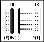 fig.tt17
The next level of difficulty comes when we decide to add another internal SCSI device, like another hard drive. Figure TT18 illustrates the proper placement of Terminating Resistors in this situation. The Host Adapter, and the device furthest away from the Host Adapter are the electrical ends of the SCSI bus, and thus retain their Terminating Resistors, while the device between these has it's Terminating Resistors removed.
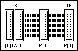 fig.
tt18
fig.
tt18OK, so you absorbed that one. Let's get a little more complex. You say you just got an external SCSI Tape drive, picked up the correct SCSI cable, and you're just itching to start backing-up your system? Don't forget to add that External cable and device into the terminating scheme! Figure TT19 illustrates the proper termination for a Host Adapter that has both Internal and external SCSI devices attached. In this situation, the Host Adapter looks like just another device positioned between the Internal and External drives. It no longer is considered an end and thus has it's Terminating Resistors removed. The two drives are now the ends of the SCSI bus, and their Terminating Resistors are retained.
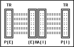 fig.
tt19
fig.
tt19Taking this to it's logical end, we can now combine the multiple internal SCSI devices with our external device, and come up with the situation illustrated in figure TT20.
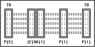 fig.
tt20
fig.
tt20Well, let's hope you're not lost, because if you are, then I haven't been clear enough. If that's the case, email me, and I'll try to help (time permitting).
One last example. Many peripheral devices have 2 SCSI connectors on them to help you extend the SCSI bus when you want to add another device. I like to refer to these as Daisy connectors... They allow you to Daisy-Chain other SCSI devices to the bus. Since the two connectors look like the same point electrically, you should treat them accordingly. Thus, if you had an internal device with a Daisy connector, and added another SCSI cable to continue the SCSI bus to another device, you'd have the situation illustrated in figure TT21.
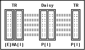 fig. tt21