SHUTTLE COMPUTER INTERNATIONAL, INC.
AE14 (PCI/ISA)
| Device Type | Mainboard |
| Processor | Celeron |
| Processor Speed | 300/333/366/400/433/466/500MHz |
| Chip Set | Intel 810 |
| Video Chip Set | Intel 810 |
| Maximum Onboard Memory | 512MB (SDRAM supported) |
| Maximum Video Memory | Unidentified |
| Cache | 128KB (located on the Celeron CPU) |
| BIOS | Award |
| Dimensions | 305mm x 170mm |
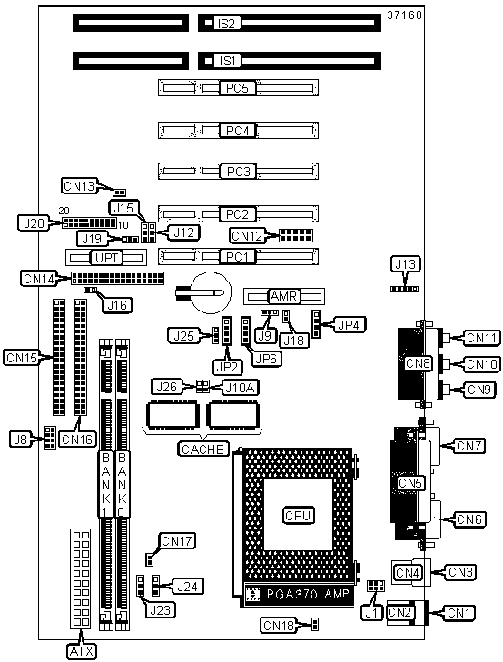
| I/O Options | 16-bit ISA slots (2), 32-bit PCI slots (5), ATX power connector, Audio in - CD-ROM, Audio/Modem Riser slot, Auxillary audio in, Floppy drive interface, Game/MIDI port, IDE interfaces (2), IR connector, Line in, Line out, Microphone in, Parallel port, PS/2 keyboard port, PS/2 mouse port, Serial interface, Serial port, TAD in, UPT slot, USB ports (2), VGA port, Wake-on-LAN connector |
CONNECTIONS |
|||
Purpose |
Location |
Purpose |
Location |
| Audio/modem riser slot | AMR | System fan power B | CN17 |
| ATX power connector | ATX | CPU fan power | CN18 |
| PS/2 keyboard port | CN1 | 16-bit ISA slots | IS1 - IS2 |
| PS/2 mouse port | CN2 | IR connector | J13 |
| USB port 1 | CN3 | Wake-on-LAN connector | J19 |
| USB port 2 | CN4 | Reset switch | J20/Pins 1 & 2 |
| Parallel port | CN5 | IDE interface LED | J20/Pins 3 & 4 |
| Serial port | CN6 | Green PC connector | J20/Pins 5 & 6 |
| VGA port | CN7 | Green PC LED connector | J20/Pins 7 & 8 |
| Game/MIDI port | CN8 | Power switch | J20/Pins 9 & 10 |
| Line out | CN9 | Speaker | J20/Pins 11 - 14 |
| Line in | CN10 | Power LED | J20/Pins 18 - 20 |
| Microphone in | CN11 | Auxiliary audio in | JP2 |
| Serial interface | CN12 | TAD in | JP4 |
| System fan power A | CN13 | Audio in - CD ROM | JP6 |
| Floppy drive interface | CN14 | 32-bit PCI slots | PC1 - PC5 |
| IDE interface 1 | CN15 | UPT slot | UPT |
| IDE interface 2 | CN16 | ||
USER CONFIGURABLE SETTINGS |
|||
Function |
Label |
Position |
|
| » | Secondary audio/modem riser slot selected | J9 | Pins 1 & 2 closed |
| Primary audio/modem riser slot selected | J9 | Pins 2 & 3 closed | |
| » | 66MHz based processor normal bus speed | J10A | Closed |
| 66MHz based processor overclocked to 100MHz | J10A | Open | |
» |
CMOS memory normal operation | J12 | Pins 1 & 2 closed |
| CMOS memory clear | J12 | Pins 2 & 3 closed | |
| » | Password normal | J15 | Pins 1 & 2 closed |
| Password clear | J15 | Pins 2 & 3 closed | |
| » | BIOS boot block protection disabled | J16 | Closed |
| BIOS boot block protection enabled | J16 | Open | |
| » | Factory configured - do not alter | J18 | Open |
| » | Suspend to RAM enabled | J23 | Pins 2 & 3 closed |
| Suspend to RAM disabled | J23 | Pins 1 & 2 closed | |
| » | 3.3V supplied to ICH | J25 | Pins 1 & 2 closed |
| 3.9V supplied to ICH | J25 | Pins 2 & 3 closed | |
| » | 100MHz based processor normal bus speed | J26 | Closed |
| 100MHz based processor overclocked to 133MHz | J26 | Open | |
| Note: When
overclocking jumper is used, J8 must be set accordingly. Note: Onboard CODEC must be disabled in BIOS when using primary AMR setting. |
|||
DIMM CONFIGURATION |
||
Size |
Bank 0 |
Bank 1 |
8MB |
(1) 1M x 64 |
None |
16MB |
(1) 1M x 64 |
(1) 1M x 64 |
16MB |
(1) 2M x 64 |
None |
24MB |
(1) 2M x 64 |
(1) 1M x 64 |
32MB |
(1) 2M x 64 |
(1) 2M x 64 |
32MB |
(1) 4M x 64 |
None |
40MB |
(1) 4M x 64 |
(1) 1M x 64 |
48MB |
(1) 4M x 64 |
(1) 2M x 64 |
64MB |
(1) 4M x 64 |
(1) 4M x 64 |
64MB |
(1) 8M x 64 |
None |
72MB |
(1) 8M x 64 |
(1) 1M x 64 |
80MB |
(1) 8M x 64 |
(1) 2M x 64 |
96MB |
(1) 8M x 64 |
(1) 4M x 64 |
128MB |
(1) 8M x 64 |
(1) 8M x 64 |
128MB |
(1) 16M x 64 |
None |
136MB |
(1) 16M x 64 |
(1) 1M x 64 |
144MB |
(1) 16M x 64 |
(1) 2M x 64 |
160MB |
(1) 16M x 64 |
(1) 4M x 64 |
192MB |
(1) 16M x 64 |
(1) 8M x 64 |
256MB |
(1) 16M x 64 |
(1) 16M x 64 |
256MB |
(1) 32M x 64 |
None |
264MB |
(1) 32M x 64 |
(1) 1M x 64 |
272MB |
(1) 32M x 64 |
(1) 2M x 64 |
288MB |
(1) 32M x 64 |
(1) 4M x 64 |
320MB |
(1) 32M x 64 |
(1) 8M x 64 |
384MB |
(1) 32M x 64 |
(1) 16M x 64 |
512MB |
(1) 32M x 64 |
(1) 32M x 64 |
| Note: Board supports SDRAM memory. | ||
CACHE CONFIGURATION |
| Note: 128KB cache is located on Celeron 300A and greater CPUs. |
CPU CLOCK SPEED SELECTION |
|||||
Clock Speed |
J8/Pins 1 & 2 |
J8/Pins 3 & 4 | J8/Pins 5 & 6 | J8/Pins 7 & 8 |
|
| » | 66MHz | Open | Open | Open | Open |
70MHz |
Closed | Open | Open | Open | |
75MHz |
Closed | Closed | Closed | Closed | |
| 83MHz | Closed | Closed | Closed | Open | |
| 90MHz | Closed | Closed | Open | Closed | |
| 95MHz | Closed | Closed | Open | Open | |
| 100MHz | Open | Open | Closed | Open | |
| 105MHz | Open | Open | Open | Closed | |
| 114MHz | Closed | Open | Open | Closed | |
| 124MHz | Open | Closed | Closed | Open | |
| 133MHz | Open | Closed | Open | Closed | |
Note: 140MHz and 150MHz are set in the BIOS. |
|||||
POWER-ON BY KEYBOARD/MOUSE SELECTION |
||
Function |
J1 |
|
| » | Power-on by mouse enabled | Pins 1 & 3, 4 & 6 closed |
| Power-on by keyboard enabled | Pins 2 & 4, 3 & 5 closed | |
| Power-on by keyboard/mouse disabled | Pins 1 & 3, 2 & 4 closed | |
CPU CORE VOLTAGE SELECTION |
||
Setting |
J24 |
|
| » | Auto detect CPU core voltage | Open |
| Increase voltage by 2% | Pins 1 & 2 closed | |
| Increase voltage by 5% | Pins 2 & 3 closed | |