J-MARK COMPUTER CORPORATION
J-6ZXAN, J-6ZXAN/L
| Device Type | Mainboard |
| Processor | Celeron |
| Processor Speed | 300/333/366/400MHz |
| Chip Set | Intel 440ZX |
| Maximum Onboard Memory | 512MB (EDO supported) |
| Cache | 0/128KB (located on Celeron CPU) |
| BIOS | Unidentified |
| Dimensions | 305mm x 170mm |
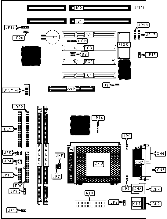
| I/O Options | 16-bit ISA slots (2), 32-bit PCI slots (4), floppy drive interface, green PC connector, IDE interfaces (2), parallel port, PS/2 mouse port, serial ports (2), IR connector, USB ports (2), ATX power connector, AGP slot |
CONNECTIONS |
|||
| Purpose | Location |
Purpose | Location |
| AGP slot | AGP |
Green PC connector | JP4/Pins 2 & 4 |
| ATX power connector | ATX |
Power on connector | JP5/Pins 2 & 4 |
| PS/2 mouse port | CN1 |
CPU fan power | JP8 |
| PS/2 keyboard port | CN2 |
SPDIF connector | JP9 |
| USB port 1 | CN3 |
Power LED & keylock | JP10/Pins 1 - 5 |
| USB port 2 | CN4 |
Turbo switch | JP10/Pins 6 - 8 |
| Serial port 1 | CN5 |
Speaker | JP10/Pins 9 - 12 |
| Serial port 2 | CN6 |
Reset switch | JP10/Pins 13 & 14 |
| Parallel port | CN7 |
Turbo LED | JP10/Pins 15 & 16 |
| Floppy drive interface | FDC |
CIR connector | JP17 |
| IDE interface 2 | IDE1 |
IR connector | JP18 |
| IDE interface 1 | IDE2 |
32-bit PCI slots | PC1 – PC4 |
| 16-bit ISA slots | IS1 – IS2 |
SB-Link connector | SB |
| System fan power | JP3 |
Wake-on-LAN connector | WON |
| IDE interface LED | JP4/Pins 1 & 3 |
||
USER CONFIGURABLE SETTINGS |
|||
Function |
Label |
Position |
|
» |
Factory configured - do not alter | J8 |
Unidentified |
» |
Factory configured - do not alter | JP1 |
Unidentified |
| Power on Keyboard enabled | JP2 |
Pins 2 & 3 closed |
|
| Power on Keyboard disabled | JP2 |
Pins 1 & 2 closed |
|
» |
Factory configured - do not alter | JP7 |
Unidentified |
» |
Factory configured - do not alter | JP15 |
Unidentified |
» |
Factory configured - do not alter | JP20 |
Unidentified |
DIMM CONFIGURATION |
||
Size |
Bank 0 |
Bank 1 |
16MB |
(1) 2M x 64 |
None |
32MB |
(1) 2M x 64 |
(1) 2M x 64 |
32MB |
(1) 4M x 64 |
None |
48MB |
(1) 4M x 64 |
(1) 2M x 64 |
64MB |
(1) 4M x 64 |
(1) 4M x 64 |
64MB |
(1) 8M x 64 |
None |
80MB |
(1) 8M x 64 |
(1) 2M x 64 |
96MB |
(1) 8M x 64 |
(1) 4M x 64 |
128MB |
(1) 8M x 64 |
(1) 8M x 64 |
128MB |
(1) 16M x 64 |
None |
144MB |
(1) 16M x 64 |
(1) 2M x 64 |
160MB |
(1) 16M x 64 |
(1) 4M x 64 |
192MB |
(1) 16M x 64 |
(1) 8M x 64 |
256MB |
(1) 16M x 64 |
(1) 16M x 64 |
256MB |
(1) 32M x 64 |
None |
272MB |
(1) 32M x 64 |
(1) 2M x 64 |
288MB |
(1) 32M x 64 |
(1) 4M x 64 |
320MB |
(1) 32M x 64 |
(1) 8M x 64 |
384MB |
(1) 32M x 64 |
(1) 16M x 64 |
512MB |
(1) 32M x 64 |
(1) 32M x 64 |
Note: Board supports EDO memory. |
||
CACHE CONFIGURATION |
| Note: 128KB cache is located on the Celeron 300A CPU and newer CPUs. |
CPU SPEED SELECTION |
|||||||
CPU speed |
Clock speed |
Multiplier |
JP6 |
U15/1 |
U15/2 |
U15/3 |
U15/4 |
300MHz |
66MHz |
4.5x |
2 & 3 |
Off |
On |
Off |
On |
333MHz |
66MHz |
5x |
2 & 3 |
Off |
Off |
Off |
On |
366MHz |
66MHz |
5.5x |
2 & 3 |
Off |
Off |
Off |
On |
400MHz |
66MHz |
6x |
2 & 3 |
On |
On |
On |
Off |
| Note: Pins designated should be in the closed position. | |||||||
CMOS/BATTERY SELECTION |
||
Setting |
JP19 |
|
| » | CMOS memory normal operation |
Pins 2 & 3 closed |
CMOS memory clear |
Pins 3 & 4 closed |
|
External battery installed |
Connect battery leads to pins 1 & 4 |
|