BLUE CHIP TECHNOLOGY, LTD.
PX1
| Device Type | Single Board Computer |
| Processor | Pentium/Pentium MMX |
| Processor Speed | 75/90/100/120/133/150/166MHz |
| Chip Set | Intel 430FX |
| Video Chip Set | S3, INC. |
| Maximum Onboard Memory | 128MB (EDO & FPM DRAM supported) |
| Maximum Video Memory | 2MB (DRAM supported) |
| Cache | 0/256/512KB |
| BIOS | AMI |
| Dimensions | 338mm x 122mm |
| I/O Options | Cache slot, Floppy drive interface, IDE interfaces (2), Parallel interface, PC/104 connectors (2), PS/2 keyboard port, PS/2 mouse port, Serial interfaces (2), Serial port, VGA feature connector, VGA port |
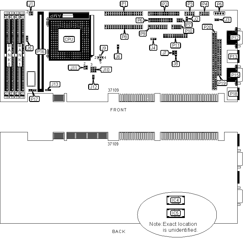
CONNECTIONS |
|||
| Purpose | Location |
Purpose | Location |
| VGA port | P12 | Parallel interface | P6 |
| PS/2 mouse port | P13 | EPLD program connector | P7 |
| RS232 serial port | P15 | IDE interface 2 | P8 |
| PS/2 keyboard port | P18 | Utility connector | P9 |
| IDE interface 1 | P1 | Security/monitor connector | P10 |
| Floppy drive interface | P2 | Video feature connector | P11 |
| RS485 serial interface 1 | P3 | External battery connector | P17 |
| RS232 serial interface 2 | P4 | 16-bit PC/104 connector | P19 |
| 5v/12v auxiliary power | P5 | 8-bit PC/104 connector | P20 |
| Note: EPLD program connector (P7) is for manufacturing use only. | |||
USER CONFIGURABLE SETTINGS |
|||
Function |
Label |
Position |
|
| RS485 serial interface termination disabled | J2 |
Open | |
| RS485 serial interface termination enabled | J2 |
Closed | |
| Onboard speaker disabled | J3 | Open | |
| Onboard speaker enabled | J3 | Closed | |
| Video memory type select Fast Page | J4 | Pins 1 & 2 closed | |
| Video memory type select EDO | J4 | Pins 2 & 3 closed | |
| » | DRAM/cache voltage select 5V | J5 | Pins 1 & 2 closed |
| DRAM/cache voltage select 3V | J5 | Pins 2 & 3 closed | |
| Onboard video enabled | J6 | Open | |
| Onboard video disabled | J6 | Closed | |
| » | BIOS ROM type select EPROM | J7 | Open |
| BIOS ROM type select Flash PROM | J7 | Closed | |
| » | BIOS memory select 5V Flash or EPROM | J8 | Open |
| BIOS memory select 12V Flash | J8 | Pins 1 & 2 closed | |
| Pentium CPU selected | J10 | Pins 1 & 2, 4 & 5, 7 & 8 closed | |
| Pentium MMX CPU selected | J10 | Pins 2 & 3, 5 & 6, 8 & 9 closed | |
| ISA bus speed / 6 selected | J12 | Open | |
| ISA bus speed / 8 selected | J12 |
Closed | |
| » | CMOS memory normal operation | J13 |
Pins 2 & 3 closed |
| CMOS memory clear | J13 |
Pins 1 & 2 closed | |
| Note: ISA bus speed is dependant of bus frequency. | |||
SIMM CONFIGURATION |
||
Size |
Bank 0 |
Bank 1 |
8MB |
(2) 1M x 32 |
None |
16MB |
(2) 2M x 32 |
None |
16MB |
(2) 1M x 32 |
(2) 1M x 32 |
24MB |
(2) 2M x 32 |
(2) 1M x 32 |
32MB |
(2) 4M x 32 |
None |
32MB |
(2) 2M x 32 |
(2) 2M x 32 |
40MB |
(2) 4M x 32 |
(2) 1M x 32 |
48MB |
(2) 4M x 32 |
(2) 2M x 32 |
64MB |
(2) 8M x 32 |
None |
64MB |
(2) 4M x 32 |
(2) 4M x 32 |
72MB |
(2) 8M x 32 |
(2) 1M x 32 |
80MB |
(2) 8M x 32 |
(2) 2M x 32 |
96MB |
(2) 8M x 32 |
(2) 4M x 32 |
128MB |
(2) 8M x 32 |
(2) 8M x 32 |
| Note: Board accepts EDO & Fast Page memory. | ||
CACHE CONFIGURATION |
|
Size |
P16 |
| 0 | No modules installed |
256KB |
256KB module installed |
512KB |
512KB module installed |
| Note: 256KB module may be asynchronous or synchronous cache. 512KB module must be synchronous cache only. | |
VIDEO MEMORY CONFIGURATION |
||
Size |
IC4 |
IC5 |
1MB |
No chips installed |
No chips installed |
2MB |
256K x 16 |
256K x 16 |
| Note: Chips must be installed in pairs. | ||
CPU SPEED SELECTION |
||||||
CPU Speed |
Bus Speed |
Multiplier |
J1/Pins 1 & 2 | J1/Pins 3 & 4 | J11/Pins 1 & 2 | J11/Pins 3 & 4 |
| 75MHz | 50MHz | 1.5x | Open | Open | Closed | Closed |
| 90MHz | 60MHz | 1.5x | Open | Open | Closed | Open |
| 100MHz | 66MHz | 1.5x | Open | Open | Open | Closed |
| 120MHz | 60MHz | 2.0x | Open | Closed | Closed | Open |
| 133MHz | 66MHz | 2.0x | Open | Closed | Open | Closed |
| 150MHz | 60MHz | 2.5x | Closed | Closed | Closed | Open |
| 166MHz | 66MHz | 2.5x | Closed | Closed | Open | Closed |
CPU VOLTAGE SELECTION |
|
Setting |
J9 |
| 2.9V | Pins 1 & 3 closed |
| 3.3V | Pins 3 & 4 closed |
| 3.45V | Pins 3 & 5 closed |
| 3.6V | Pins 2 & 3 closed |
DIAGNOSTIC LED(S) |
|||
LED |
Color |
Status |
Condition |
| D1 | Yellow | On | Watchdog timeout has occurred |
| D1 | Yellow | Off | Watchdog timeout has not occurred |
| D2 | Yellow | On | Monitor microcontroller error has occurred |
| D2 | Yellow | Off | Monitor microcontroller error has not occurred |
| D3 | Red | On | Reset in process |
| D3 | Red | Off | Reset not in process |
| D4 | Yellow | On | IDE activity detected |
| D4 | Yellow | Off | IDE activity not detected |
D5 |
Green |
On |
- 5V power supply detected |
D5 |
Green |
Off |
- 5V power supply not detected |
D6 |
Green |
On |
- 12V power supply detected |
D6 |
Green |
Off |
- 12V power supply not detected |
| D7 | Green | On | + 12V power supply detected |
| D7 | Green | Off | + 12V power supply not detected |
| D8 | Green | On | + 5V power supply detected |
| D8 | Green | Off | + 5V power supply not detected |
| D9 | Green | On | 3.3V host CPU I/O and chipset supply detected |
| D9 | Green | Off | 3.3V host CPU I/O and chipset supply not detected |
| D10 | Red | On | MSB POST data bit is 1 |
| D10 | Red | Off | MSB POST data bit is not 1 |
| D11 | Red | On | Unidentified POST data bit is 1 |
| D11 | Red | Off | Unidentified POST data bit is not 1 |
| D12 | Red | On | Unidentified POST data bit is 1 |
| D12 | Red | Off | Unidentified POST data bit is not 1 |
| D13 | Red | On | Unidentified POST data bit is 1 |
| D13 | Red | Off | Unidentified POST data bit is not 1 |
| D14 | Red | On | Unidentified POST data bit is 1 |
| D14 | Red | Off | Unidentified POST data bit is not 1 |
| D15 | Red | On | Unidentified POST data bit is 1 |
| D15 | Red | Off | Unidentified POST data bit is not 1 |
| D16 | Red | On | Unidentified POST data bit is 1 |
| D16 | Red | Off | Unidentified POST data bit is not 1 |
| D17 | Red | On | LSB POST data bit is 1 |
| D17 | Red | Off | LSB POST data bit is not 1 |
Note: Diagram of LEDs not available. |
|||
MISCELLANEOUS TECHNICAL NOTES |
| Board contains Solid State Disk
Flash and SRAM sockets. Diagram and configuration not available. Board will support up to 14 ISA slots and 3 PCI slots (1 shared). 3 PC/104 devices can attach on board without occupying a backplane bus slot. |