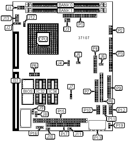
BLUE CHIP TECHNOLOGY, LTD.
APEX II
| Device Type | Single Board Computer |
| Processor | 80486SX/80486DX/80486DX2/80486DX4/P24T |
| Processor Speed | 16/25/33/40/50/66MHz |
| Chip Set | Unidentified |
| Video Chip Set | Cirrus Logic |
| Maximum Onboard Memory | 16MB |
| Maximum Video Memory | 512KB |
| Cache | Unidentified |
| BIOS | AMI |
| Dimensions | 204mm x 147mm |
| I/O Options | 16-bit ISA slot, AT/PS/2 keyboard interface, Auxiliary power connector, External battery connector, Digital I/O port interface, Flat panel connector, Floppy drive interface, IDE interface, Parallel interface, PC/104 connectors (2), POST interface, Power connector, PS/2 mouse interface, Serial interfaces (3), Video interface |

CONNECTIONS |
|||
| Purpose | Location |
Purpose | Location |
| 16-bit ISA slot | IS1 | RS232 serial interface 1 | P10 |
| Flat panel connector | P1 | RS232 serial interface 2 | P11 |
| Video interface | P2 | RS485 serial interface 1 & 2 | P12 |
| IDE interface | P3 | 5v/12v main power | P13 |
| Peripheral/utilities interface | P4 | 8-bit PC/104 connector | P15 |
| POST interface | P6 | External battery connector | P16 |
| Parallel interface | P7 | 16-bit PC/104 connector | P17 |
| Floppy drive interface | P8 | Auxiliary power | P19 |
| Digital I/O port interface | P9 | ||
USER CONFIGURABLE SETTINGS |
|||
Function |
Label |
Position |
|
| 486DX CPU | J2 |
Pins 1 & 2, 3 & 4 closed | |
| 486SX CPU | J2 |
Pins 2 & 3 closed | |
| Onboard video disabled | J4 | Pins 1 & 2 closed | |
| Onboard video enabled | J4 | Pins 2 & 3 closed | |
| » | Factory configured - do not alter | J5 | Unidentified |
| IDE interface not grounded | J6 | Open | |
| IDE interface grounded | J6 | Closed | |
| Parallel interface IRQ select IRQ7 (LPT1) | J7 | Pins 1 & 2 closed | |
| Parallel interface IRQ select IRQ5 (LPT2) | J7 |
Pins 2 & 3 closed | |
| External battery selected | J8 |
Pins 1 & 2 closed | |
| Internal battery selected | J8 |
Pins 2 & 3 closed | |
» |
CMOS/SRAM memory normal operation | J9 |
Pins 1 & 2 closed |
| CMOS/SRAM memory clear | J9 |
Pins 2 & 3 closed | |
| RS485 serial interface 1 full duplex | J10 |
Open | |
| RS485 serial interface 1 half duplex controlled by DTR | J10 |
Closed | |
| RS485 serial interface 2 full duplex | J11 |
Open | |
| RS485 serial interface 2 half duplex controlled by DTR | J11 |
Closed | |
| 486SX or 486DX CPU | J12 | Pins 1 & 2 closed | |
| P24T CPU | J12 | Pins 2 & 3 closed | |
| CPU voltage select 3.3v | J13 | Open | |
| CPU voltage select 5v | J13 |
Pins 1 & 2, 3 & 4,5 & 6, 7 & 8 closed | |
SIMM CONFIGURATION |
||
Size |
Bank 0 |
Bank 1 |
1MB |
(1) 256K x 36 |
None |
2MB |
(1) 256K x 36 |
(1) 256K x 36 |
4MB |
(1) 1M x 36 |
None |
5MB |
(1) 1M x 36 |
(1) 256K x 36 |
8MB |
(1) 1M x 36 |
(1) 1M x 36 |
16MB |
(1) 4M x 36 |
None |
16MB |
None |
(1) 4M x 36 |
FLASH MEMORY CONFIGURATION |
|
Size |
IC32 |
| 1024KB | Open |
| 1152KB | 128KB chip installed |
1280KB |
256KB chip installed |
1536KB |
512KB chip installed |
| 2048KB | 1024KB chip installed via PCB |
| 3072KB | (2) 1024KB chips installed via PCB |
Note: PCB connects to IC32. Optional flash memory card can connect to PCB. Diagram of PCB not available. |
|
SRAM CONFIGURATION |
|
Size |
IC34 |
128KB |
128KB chip installed |
512KB |
512KB chip installed |
CPU SPEED SELECTION |
||||
CPU Speed |
J1/Pins 1 & 2 |
J1/Pins 3 & 4 | J1/Pins 5 & 6 | J1/Pins 7 & 8 |
16MHz |
Closed | Closed | Closed | Open |
25MHz |
Closed | Open | Closed | Open |
| 33MHz | Open | Open | Closed | Open |
| 40MHz | Closed | Closed | Open | Open |
| 50MHz | Open | Closed | Open | Open |
| 66MHz | Closed | Open | Open | Open |
FLAT PANEL DISPLAY SELECTION |
|||
Display Type |
J3/Pins 1 & 2 |
J3/Pins 3 & 4 | J3/Pins 5 & 6 |
TFT mode selected |
Open | Open | Closed |
Monochrome mode selected |
Open | Closed | Closed |
| STN dual scan mode selected | Closed | Open | Closed |
| STN single scan mode selected | Closed | Closed | Closed |