GIGA-BYTE TECHNOLOGY CO., LTD.
GA-6WMM7 (REV. 1.5)
| Device Type | Mainboard |
| Processor | Celeron |
| Processor Speed | 200/233/266/300/333/366/400/433/466/500/533MHz |
| Chip Set | Intel 810 |
| Video Chip Set | Unidentified |
| Audio Chip Set | Yamaha |
| Maximum Onboard Memory | 512MB (SDRAM supported) |
| Maximum Video Memory | 4MB |
| Maximum Audio Memory | Unidentified |
| Cache | 0/128KB (located on the Celeron CPU) |
| BIOS | Award |
| Dimensions | 244mm x 232mm |
| I/O Options | 16-bit ISA slot, 32-bit PCI slots (3), Audio/Modem Riser slot, ATX power connector, audio in - CD-ROM, auxiliary in, digital flat panel connector, floppy drive interface, front panel USB interface, game/MIDI port, green PC connector, IDE interfaces (2), IR connector, line in, line out, microphone in, parallel port, PS/2 keyboard port, PS/2 mouse port, serial interface, serial port, SPDIF connector, STR LED connector, USB ports (2), VGA port, voice modem connector, Wake-on-LAN connector, Wake-on-modem connector |
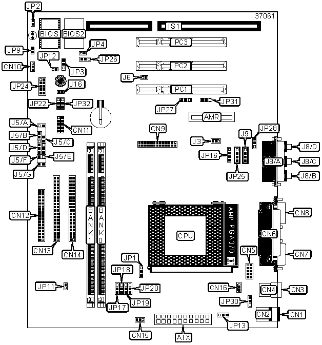
CONNECTIONS |
|||
Purpose |
Location |
Purpose |
Location |
| Audio/modem riser slot | AMR | Green LED | J5/A |
| ATX power connector | ATX | Reset switch | J5/B |
| PS/2 keyboard port | CN1 | Power switch | J5/C |
| PS/2 mouse port | CN2 | Speaker | J5/D |
| USB port 1 | CN3 | Power LED | J5/E |
| USB port 2 | CN4 | IDE interface LED | J5/F |
| Serial interface 2 | CN5 | Green PC switch | J5/G |
| Parallel port | CN6 | Wake-on-modem connector | J6 |
| Serial port 1 | CN7 | Game/MIDI port | J8/A |
| VGA port | CN8 | Line out | J8/B |
| Digital flat panel connector | CN9 | Line in | J8/C |
| System fan power | CN10 | Microphone in | J8/D |
| IR connector | CN11 | Audio in - CD-ROM | J9 |
| Floppy drive interface | CN12 | STR LED connector | JP9 |
| IDE interface 1 | CN13 | Chassis intrusion connector | JP12 |
| IDE interface 2 | CN14 | Voice modem connector | JP16 |
| Power supply fan power | CN15 | Front panel USB interface | JP24 |
| CPU fan power | CN16 | Auxiliary in | JP25 |
| 16-bit ISA slot | IS1 | SPDIF connector | JP28 |
| Wake-on-LAN connector | J3 | 32-bit PCI slots | PC1 - PC3 |
USER CONFIGURABLE SETTINGS |
|||
Function |
Label |
Position |
|
| Buzzer enabled | J16 | Closed | |
| Buzzer disabled | J16 | Open | |
| » | Table is locked | JP2 | Open |
| Table is unlocked | JP2 | Closed | |
» |
CMOS memory normal operation | JP3 | Pins 2 & 3 closed |
| CMOS memory clear | JP3 | Pins 1 & 2 closed | |
| Reboot on timeout | JP4 | Open | |
| Do not reboot on timeout | JP4 | Closed | |
| STR disabled | JP11 | Open | |
| STR enabled | JP11 | Closed | |
| » | Power-on by keyboard disabled | JP13 | Pins 2 & 3 closed |
| Power-on by keyboard enabled | JP13 | Pins 1 & 2 closed | |
| » | Onboard audio enabled | JP27 | Pins 2 & 3 closed |
| Onboard audio disabled | JP27 | Pins 1 & 2 closed | |
| Wake-on-USB keyboard disabled | JP30 | Pins 1 & 2 closed | |
| Wake-on-USB keyboard enabled | JP30 | Pins 2 & 3 closed | |
DIMM CONFIGURATION |
||
Size |
Bank 0 |
Bank 1 |
8MB |
(1) 1M x 64 |
None |
16MB |
(1) 1M x 64 |
(1) 1M x 64 |
16MB |
(1) 2M x 64 |
None |
24MB |
(1) 2M x 64 |
(1) 1M x 64 |
32MB |
(1) 2M x 64 |
(1) 2M x 64 |
32MB |
(1) 4M x 64 |
None |
40MB |
(1) 4M x 64 |
(1) 1M x 64 |
48MB |
(1) 4M x 64 |
(1) 2M x 64 |
64MB |
(1) 4M x 64 |
(1) 4M x 64 |
64MB |
(1) 8M x 64 |
None |
72MB |
(1) 8M x 64 |
(1) 1M x 64 |
80MB |
(1) 8M x 64 |
(1) 2M x 64 |
96MB |
(1) 8M x 64 |
(1) 4M x 64 |
128MB |
(1) 8M x 64 |
(1) 8M x 64 |
128MB |
(1) 16M x 64 |
None |
136MB |
(1) 16M x 64 |
(1) 1M x 64 |
144MB |
(1) 16M x 64 |
(1) 2M x 64 |
160MB |
(1) 16M x 64 |
(1) 4M x 64 |
192MB |
(1) 16M x 64 |
(1) 8M x 64 |
256MB |
(1) 16M x 64 |
(1) 16M x 64 |
256MB |
(1) 32M x 64 |
None |
264MB |
(1) 32M x 64 |
(1) 1M x 64 |
272MB |
(1) 32M x 64 |
(1) 2M x 64 |
288MB |
(1) 32M x 64 |
(1) 4M x 64 |
320MB |
(1) 32M x 64 |
(1) 8M x 64 |
384MB |
(1) 32M x 64 |
(1) 16M x 64 |
512MB |
(1) 32M x 64 |
(1) 32M x 64 |
| Note: Board
supports SDRAM memory. Note: PC100 modules must be used. |
||
CACHE CONFIGURATION |
| Note: 128KB cache is located on Celeron 300A and greater CPUs. |
SYSTEM BUS FORCED SPEED SELECTION |
|
Setting |
JP1 |
Auto |
Pins 1 & 2 closed |
Force 66MHz |
Pins 2 & 3 closed |
Force 100MHz |
Open |
SYSTEM BUS SPEED SELECTION |
||||||
CPU |
SDRAM |
PCI |
JP17 |
JP18 | JP19 | JP20 |
| Auto | 100 | 33 | 2 & 3 | 2 & 3 | Open | Open |
| 150 | 150 | 37.5 | 1 & 2 | 2 & 3 | 2 & 3 | 1 & 2 |
| 140 | 140 | 35 | 1 & 2 | 2 & 3 | 2 & 3 | 2 & 3 |
| 133.3 | 133.3 | 44.43 | 2 & 3 | 1 & 2 | 1 & 2 | 2 & 3 |
| 133.3 | 133.3 | 33.32 | 2 & 3 | 1 & 2 | 1 & 2 | 1 & 2 |
| 124 | 124 | 41.33 | 2 & 3 | 1 & 2 | 2 & 3 | 1 & 2 |
| 120 | 120 | 40 | 2 & 3 | 1 & 2 | 2 & 3 | 2 & 3 |
| 114.99 | 114.99 | 38.33 | 1 & 2 | 2 & 3 | 1 & 2 | 2 & 3 |
| 105 | 105 | 35 | 2 & 3 | 2 & 3 | 1 & 2 | 2 & 3 |
| 100.9 | 100.9 | 33.63 | 2 & 3 | 2 & 3 | 2 & 3 | 1 & 2 |
| 100.23 | 100.23 | 33.41 | 2 & 3 | 2 & 3 | 2 & 3 | 2 & 3 |
| 95 | 95 | 31.67 | 1 & 2 | 1 & 2 | 1 & 2 | 1 & 2 |
| 90 | 90 | 30 | 1 & 2 | 1 & 2 | 1 & 2 | 2 & 3 |
| 83.31 | 124.96 | 41.65 | 1 & 2 | 1 & 2 | 2 & 3 | 1 & 2 |
| 75 | 112.5 | 37.5 | 1 & 2 | 1 & 2 | 2 & 3 | 2 & 3 |
| 70 | 105 | 35 | 1 & 2 | 2 & 3 | 1 & 2 | 1 & 2 |
| 66.89 | 100.33 | 33.44 | 2 & 3 | 2 & 3 | 1 & 2 | 1 & 2 |
Note: Designated pins should be in the closed position. |
||||||
USB PORT SELECTION |
||
Setting |
JP22 |
JP32 |
Front panel USB selected |
Pins 1 & 2 closed |
Pins 1 & 2 closed |
Back panel USB selected |
Pins 2 & 3 closed |
Pins 2 & 3 closed |
SYSTEM BOOT SELECTION |
|
Setting |
JP26 |
Normal |
Pins 1 & 2 closed |
Safe mode |
Pins 2 & 3 closed |
Recovery |
Open |
AMR SELECTION |
||
AMR Card |
Onboard CDOEC |
JP31 |
Secondary |
Primary |
Pins 1 & 2 closed |
Primary |
Disabled |
Pins 2 & 3 closed |
| Note: AMR must be set as primary if onboard sound option is used. | ||