CONCUR SYSTEM TECHNOLOGIES
CEX-32386-1
| Device Type | Single Board Computer |
| Processor | Intel 386EX |
| Processor Speed | 33MHz |
| Chip Set | Unidentified |
| Maximum Onboard Memory | 32MB (DRAM), Unified Memory Architecture (UMA) |
| Cache | Unidentified |
| BIOS | Unidentified |
| Dimensions | 278mm x 127mm |
| I/O Options | Ethernet 10BaseT connector, serial interface, serial ports (2), AT power connector, PC/104 connectors (4), DSP ports (2), keypad connector, optical connector, LCD connector |
| NPU | TI C32 |
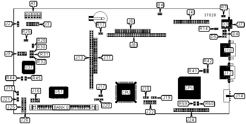
CONNECTIONS |
|||
| Purpose | Location |
Purpose | Location |
| AT Power connector | AT | C32 serial interface | J14 |
| 10BaseT connector receive LED | D3 | Backlight connector | J15 |
| 10BaseT connector transmit LED | D4 | FPGA 2 programming connector | J16 |
| 10BaseT connector link integrity LED | D5 | Reset connector | J17 |
| Optical connector | J2 | C32 reset connector | J18 |
| LCD connector | J3 | C32 timer connector | J19 |
| C32 DSP port | J4 |
JTAG connector | J20 |
| PC/104 connector (16-bit) | J6 | Power LED | J21 |
| Ethernet 10BaseT connector | J7 | C32 JTAG emulator connector | J22 |
| PC/104 connector (8-bit) | J8 | C32 DSP port | J24 |
| FPGA 1 programming connector | J9 | Passive keypad row connector | J25 |
| Serial port 1 | J10 | Passive Keypad column connector | J26 |
| PC/104 connector (16-bit) | J11 | FPGA device 1 | U37 |
| Serial port 2 | J12 | FPGA device 2 | U51 |
| PC/104 connector (8-bit) | J13 | ||
USER CONFIGURABLE SETTINGS |
|||
Function |
Label |
Position |
|
| Serial EEPROM disabled for Ethernet controller chip | R4 | Installed | |
| Serial EEPROM enabled for Ethernet controller chip | R4 | Not installed | |
| Ethernet connector reference selection ground | R7 | Installed | |
| Ethernet connector reference selection chassis ground | R7 | Not installed | |
|
Optical connector available | R25 | Installed |
| Optical connector not available | R25 | Not installed | |
SIMM CONFIGURATION |
|
Size |
Bank 0 |
4MB |
(1) 1M x 36 |
8MB |
(1) 2M x 36 |
16MB |
(1) 4M x 36 |
32MB |
(1) 8M x 36 |
LCD VOLTAGE SELECTION |
|||||
D/A Output |
Supply Voltage Required | R28 | R30 | R31 | 32 |
0v-4.096v |
0v-5v | Installed | Not installed | Installed | Not installed |
-2.048v-2.048v |
+/-12v | Not installed | Installed | Not installed | Installed |
EMULATOR PORT CLOCK SIGNAL SELECTION |
||
Setting |
R59 | R60 |
H1 |
Installed | Not installed |
H3 |
Not installed | Installed |
C32 EXTERNAL INPUT CLOCK SELECTION |
||
Setting |
R41 | R42 |
Input clock installed on TCKL0 |
Not installed | Installed |
Input clock installed on TCKL1 |
Installed | Not installed |
| Input clock not installed | Not installed | Not installed |
C32 EXTERNAL FLAG SELECTION |
||
Setting |
R14 | R17 |
External flags connected across DSP interface |
Installed | Installed |
| External flags connected for control signals to 386EX | Not installed | Not installed |
FPGA 1 CONFIGURATION |
||
Setting |
R44 | R45 |
Programmed by serial EEPROM |
Installed | Not installed |
Programmed by programming connector |
Not installed | Installed |
MISCELLANEOUS TECHNICAL NOTES |
R xx labels indicate resistors, which are installed or not installed. |