OCEAN INFORMATION SYSTEMS, INC.
BISON VI
| Device Type | Mainboard |
| Processor | Pentium |
| Processor Speed | 75/90/100MHz |
| Chip Set | Unidentified |
| Maximum Onboard Memory | 128MB (DRAM supported) |
| Cache | 2048KB |
| BIOS | Unidentified |
| Dimensions | Unidentified |
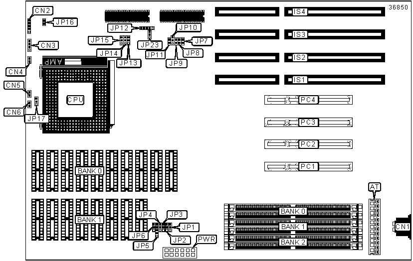
| I/O Options | 32-bit PCI slots (4), 16-bit ISA slots (4), AT keyboard port, Green PC connector |
CONNECTIONS |
|||
| Purpose | Location |
Purpose | Location |
| AT power connector | AT | Green PC switch | CN5 |
| AT keyboard port | CN1 | Green PC LED | CN6 |
| Power LED & keylock | CN2 | 16-bit ISA slots | IS1 - IS4 |
| Speaker | CN3 | 32-bit PCI slots | PC1 - PC4 |
| Reset switch | CN4 | Power connector | PWR |
USER CONFIGURABLE SETTINGS |
|||
Function |
Label |
Position |
|
» |
Factory configured - do not alter | JP10 | Unidentified |
» |
Factory configured - do not alter | JP11 | Unidentified |
| » | CPU pipeline enabled | JP14 | Pins 2 & 3 closed |
| CPU pipeline disabled | JP14 | Pins 1 & 2 closed | |
| » | CMOS memory normal operation | JP16 | Open |
| CMOS memory clear | JP16 | Closed | |
» |
Factory configured - do not alter | JP17 | Unidentified |
» |
Factory configured - do not alter | JP23 |
Closed |
SIMM CONFIGURATION |
|||
Size |
Bank 0 |
Bank 1 |
Bank 2 |
2MB |
(2) 512K x 36 |
None |
None |
4MB |
(2) 512K x 36 |
(2) 512K x 36 |
None |
4MB |
(2) 1M x 36 |
None |
None |
8MB |
(2) 2M x 36 |
None |
None |
8MB |
(2) 1M x 36 |
(2) 1M x 36 |
None |
12MB |
(2) 512K x 36 |
(2) 512K x 36 |
(2) 2M x 36 |
12MB |
(2) 1M x 36 |
None |
(2) 2M x 36 |
16MB |
(2) 1M x 36 |
(2) 1M x 36 |
None |
16MB |
(2) 2M x 36 |
None |
None |
20MB |
(2) 1M x 36 |
None |
(2) 4K x 36 |
24MB |
(2) 2M x 36 |
(2) 2M x 36 |
(2) 2M x 36 |
24MB |
(2) 4M x 36 |
None |
(2) 2M x 36 |
32MB |
(2) 8M x 36 |
None |
None |
32MB |
(2) 4M x 36 |
(2) 4M x 36 |
None |
32MB |
(2) 2M x 36 |
(2) 2M x 36 |
(2) 4M x 36 |
36MB |
(2) 512K x 36 |
(2) 512K x 36 |
(2) 8M x 36 |
36MB |
(2) 1M x 36 |
None |
(2) 8M x 36 |
38MB |
(2) 8M x 36 |
(2) 512K x 36 |
(2) 512K x 36 |
40MB |
(2) 2M x 36 |
(2) 8M x 36 |
None |
48MB |
(2) 2M x 36 |
(2) 2M x 36 |
(2) 8M x 36 |
48MB |
(2) 4M x 36 |
None |
(2) 8M x 36 |
64MB |
(2) 8M x 36 |
(2) 8M x 36 |
None |
64MB |
(2) 16M x 36 |
None |
None |
72MB |
(2) 2M x 36 |
(2) 8M x 36 |
(2) 8M x 36 |
72MB |
(2) 16M x 36 |
None |
(2) 2M x 36 |
80MB |
(2) 2M x 36 |
(2) 2M x 36 |
(2) 16M x 36 |
80MB |
(2) 8M x 36 |
(2) 8M x 36 |
(2) 4M x 36 |
96MB |
(2) 16M x 36 |
None |
(2) 8M x 36 |
96MB |
(2) 8M x 36 |
(2) 8M x 36 |
(2) 8M x 36 |
128MB |
(2) 32M x 36 |
None |
None |
128MB |
(2) 16M x 36 |
None |
(2) 16M x 36 |
CACHE JUMPER CONFIGURATION |
|||||||
Size |
JP1 | JP2 | JP3 | JP4 | JP5 | JP6 | TAG |
256KB |
1 & 2 | 1 & 2 | 1 & 2 | 1 & 2 | 1 & 2, 3 & 4 | 2 & 3 | 32K x 8 |
512KB |
2 & 3 | 1 & 2 | 1 & 2 | 2 & 3 | 2 & 3, 4 & 5 | 2 & 3 | 32K x 8 |
512KB |
2 & 3 | 1 & 2 | 1 & 2 | 1 & 2 | 1 & 2, 3 & 4 | 1 & 2 | 64K x 8 |
1MB |
2 & 3 | 2 & 3 | 1 & 2 | 2 & 3 | 2 & 3, 4 & 5 | 2 & 3 | 64K x 8 |
1MB |
2 & 3 | 2 & 3 | 1 & 2 | 1 & 2 | 1 & 2, 3 & 4 | 2 & 3 | 128K x 8 |
2MB |
2 & 3 | 2 & 3 | 2 & 3 | 2 & 3 | 2 & 3, 4 & 5 | 2 & 3 | 128K x 8 |
Note: Pins designated should be in the closed position. |
|||||||
CACHE CONFIGURATION |
||
Size |
Bank 0 |
Bank 1 |
256KB |
(8) 32K x 8 |
None |
512KB |
(8) 32K x 8 |
(8) 32K x 8 |
512KB |
(8) 64K x 8 |
None |
1MB |
(8) 64K x 8 |
(8) 64K x 8 |
1MB |
(8) 128K x 8 |
None |
2MB |
(8) 128K x 8 |
(8) 128K x 8 |
CPU CACHE WRITE BACK SELECTION |
|||
Setting |
JP13 | JP15 | |
| » | Write back | Pins 1 & 2 closed | Pins 2 & 3 closed |
| Write through | Pins 2 & 3 closed | Pins 1 & 2 closed | |
CPU SPEED SELECTION |
||||
CPU Speed |
Clock Speed | JP7 | JP8 | JP9 |
75MHz |
50MHz | Open | Open | Closed |
90MHz |
60MHz | Closed | Open | Closed |
100MHz |
66MHz | Closed | Closed | Closed |
FLASH ROM SELECTION |
||
Setting |
JP12 |
|
12V Flash ROM |
Pins 1 & 2 closed | |
5V Flash ROM |
Pins 2 & 3 closed | |
| » | Programming disabled | Pins 3 & 4 closed |
| Programmig enabled | Pins 4 & 5 closed | |