PC CHIPS MANUFACTURING, LTD
M760V (VER. 1.4)
| Device Type | Mainboard |
| Processor | Pentium II/Celeron |
| Processor Speed | 233/266/300/333/350/366/400/450/500MHz |
| Chip Set | VIA BX |
| Audio Chip Set | Sound Pro |
| Maximum Onboard Memory | 768MB (EDO & SDRAM supported) |
| Cache | 0/128/256/512KB (located on the Pentium CPU) |
| Video Memory | 8MB |
| BIOS | AMI |
| Dimensions | 244mm x 220mm |
| I/O Options | 32-bit PCI slots (3), floppy drive interface, game/MIDI port, IDE interfaces (2), parallel port, PS/2 mouse port, serial ports (2), IR connector, USB ports (2), ATX power connector, line in, line out, microphone in, audio in – CD-ROMs (2) |
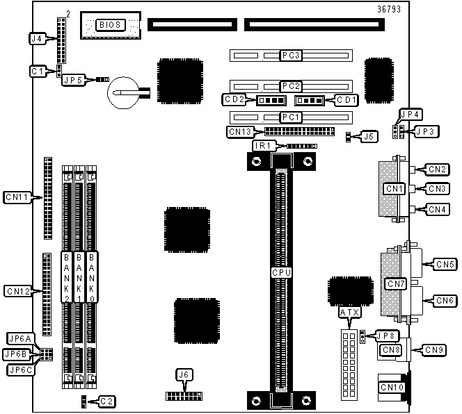
CONNECTIONS |
|||
| Purpose | Location |
Purpose | Location |
| ATX power connector | ATX |
IDE interface 2 | CN11 |
| Chassis fan power | C1 |
IDE interface 1 | CN12 |
| CPU fan power | C2 |
Floppy drive interface | CN13 |
| Audio in – CD-ROM | CD1 |
IR connector | IR1 |
| Audio in – CD-ROM | CD2 |
Speaker | J4/Pins 1, 3, 5 & 7 |
| Game/MIDI port | CN1 |
Power LED | J4/Pins 2, 4, 6, 8 & 10 |
| Line out | CN2 |
Green PC connector |
J4/Pins 13 & 14 |
| Microphone in | CN3 |
IDE interface LED | J4/Pins 15 & 16 |
| Line in | CN4 |
Reset switch | J4/Pins 17 & 18 |
| Serial port 2 | CN5 |
Power switch | J4/Pins 21 & 22 |
| Serial port 1 | CN6 |
Green PC LED | J5 |
| Parallel port | CN7 |
VGA connector | J6 |
| USB port 1 | CN8 |
Digital audio out | JP3 |
| USB port 2 | CN9 |
Digital audio in | JP4 |
| PS/2 mouse port | CN10 |
32-bit PCI slots | PC1 – PC3 |
USER CONFIGURABLE SETTINGS |
|||
Function |
Label |
Position |
|
» |
CMOS memory normal operation | JP5 |
Pins 1 & 2 closed |
| CMOS memory clear | JP5 |
Pins 2 & 3 closed |
|
» |
Keyboard power on disabled | JP8 |
Pins 2 & 3 closed |
| Keyboard power on enabled | JP8 |
Pins 1 & 2 closed |
|
DIMM CONFIGURATION |
|||
Size |
Bank 0 |
Bank 1 |
Bank 2 |
8MB |
(1) 1M x 64 |
None |
None |
16MB |
(1) 2M x 64 |
None |
None |
16MB |
(1) 1M x 64 |
(1) 1M x 64 |
None |
24MB |
(1) 2M x 64 |
(1) 1M x 64 |
None |
24MB |
(1) 1M x 64 |
(1) 1M x 64 |
(1) 1M x 64 |
32MB |
(1) 4M x 64 |
None |
None |
32MB |
(1) 2M x 64 |
(1) 1M x 64 |
(1) 1M x 64 |
32MB |
(1) 2M x 64 |
(1) 2M x 64 |
None |
48MB |
(1) 4M x 64 |
(1) 1M x 64 |
(1) 1M x 64 |
48MB |
(1) 4M x 64 |
(1) 2M x 64 |
None |
64MB |
(1) 8M x 64 |
None |
None |
64MB |
(1) 4M x 64 |
(1) 2M x 64 |
(1) 2M x 64 |
64MB |
(1) 4M x 64 |
(1) 4M x 64 |
None |
80MB |
(1) 8M x 64 |
(1) 1M x 64 |
(1) 1M x 64 |
96MB |
(1) 8M x 64 |
(1) 2M x 64 |
(1) 2M x 64 |
96MB |
(1) 4M x 64 |
(1) 4M x 64 |
(1) 4M x 64 |
128MB |
(1) 16M x 64 |
None |
None |
128MB |
(1) 8M x 64 |
(1) 4M x 64 |
(1) 4M x 64 |
128MB |
(1) 8M x 64 |
(1) 8M x 64 |
None |
144MB |
(1) 16M x 64 |
(1) 1M x 64 |
(1) 1M x 64 |
160MB |
(1) 16M x 64 |
(1) 2M x 64 |
(1) 2M x 64 |
192MB |
(1) 16M x 64 |
(1) 4M x 64 |
(1) 4M x 64 |
192MB |
(1) 8M x 64 |
(1) 8M x 64 |
(1) 8M x 64 |
256MB |
(1) 32M x 64 |
None |
None |
256MB |
(1) 16M x 64 |
(1) 8M x 64 |
(1) 8M x 64 |
272MB |
(1) 32M x 64 |
(1) 1M x 64 |
(1) 1M x 64 |
288MB |
(1) 32M x 64 |
(1) 2M x 64 |
(1) 2M x 64 |
320MB |
(1) 32M x 64 |
(1) 4M x 64 |
(1) 4M x 64 |
384MB |
(1) 32M x 64 |
(1) 8M x 64 |
(1) 8M x 64 |
384MB |
(1) 16M x 64 |
(1) 16M x 64 |
(1) 16M x 64 |
512MB |
(1) 32M x 64 |
(1) 16M x 64 |
(1) 16M x 64 |
512MB |
(1) 32M x 64 |
(1) 32M x 64 |
None |
768MB |
(1) 32M x 64 |
(1) 32M x 64 |
(1) 32M x 64 |
| Note: Board accepts EDO & SDRAM memory. | |||
DIMM VOLTAGE CONFIGURATION |
||||
Voltage |
JP6A |
JP6B |
JP6C | |
| » | 3.3v |
Pins 1 & 2 closed |
Pins 1 & 2 closed |
Pins 1 & 2 closed |
5v |
Pins 2 & 3 closed |
Pins 2 & 3 closed |
Pins 2 & 3 closed |
|
CACHE CONFIGURATION |
| Note: 256KB/512KB cache is located on the Pentium II CPUs. 128KB cache is located on the Celeron 300A and greater CPUs. |