ACER, INC.
ASPIRE 5000D, ASPIRE 5000T
| Device Type | Mainboard |
| Processor | IBM 6x86MX/AM K6/Pentium/Pentium MMX |
| Processor Speed | 166/200/233/266/300MHz |
| Chip Set | Intel 440LX |
| Video Chip Set | ATI |
| Maximum Onboard Memory | 256MB (SDRAM supported) |
| Maximum Video Memory | 2MB |
| Cache | 512KB |
| BIOS | Acer |
| Dimensions | Unidentified |
| I/O Options | floppy drive interface, IDE interfaces (2), parallel port, PS/2 mouse port, PS/2 keyboard port, serial interface, serial port, VGA port, riser slot, USB ports (2), audio in - CD-ROM, ATI AMC connector, Wake-on-LAN connector, Wake-on-ring connector, Standy-by connector |
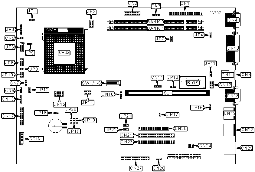
CONNECTIONS |
|||
| Purpose | Location |
Purpose | Location |
| Audio in - CD ROM | CDIN1 | PS/2 mouse port | CN19 |
| ATI AMC connector | CN1 |
Floppy drive interface | CN20 |
| Reserved | CN2 |
IDE interface 1 | CN21 |
| Reserved | CN3 | PS/2 keyboard connector | CN22 |
| VGA port | CN4 | IDE interface 2 | CN23 |
| Fan power | CN5 | Reserved | CN24 |
| USB port 2 | CN6 | Reserved | CN25 |
| Reserved | CN7 | Reserved | CN27 |
| Reset switch | CN9 | Stand-by connector | CN28 |
| Parallel port | CN10 | Fan power | JP3 |
| USB port 1 | CN11 | IDE interface LED | JP8/Pins 1 & 3 |
| Serial interface | CN12 | Power message LED | JP8/Pins 2, 4, 6 |
| Reserved | CN13 | Power switch | JP8/Pins 7 & 8 |
| Wake-on-LAN connector | CN14 | Power switch | JP9 |
| Voltage select connector | CN15 | Power LED | JP10/Pins 2 & 4 |
| Wake-on-ring connector | CN16 | IDE interface message LED | JP10/Pins 1, 3, 5 |
| Reserved | CN17 | Reserved | JP17 |
| Serial port | CN18 | Riser slot | SL1 |
| Note: The location of Pin 1 on JP10 is unidentified. | |||
USER CONFIGURABLE SETTINGS |
|||
Function |
Label |
Position |
|
| » | IRQ enabled | JP4 | Pins 2 & 3 closed |
| IRQ disabled | JP4 | Pins 1 & 2 closed | |
| » | On-board video enabled | JP7 | Pins 2 & 3 closed |
| On-board video disabled | JP7 | Pins 1 & 2 closed | |
| » | Flash BIOS voltage select 5v | JP11 | Pins 2 & 3 closed |
| Flash BIOS voltage select 12v | JP11 | Pins 1 & 2 closed | |
| » | Support for SMM switch | JP12 | Pins 1 & 2 closed |
| Support for reset switch | JP12 | Pins 2 & 3 closed | |
| » | Boot block enabled | JP13 | Pins 2 & 3 closed |
| Boot block disabled | JP13 | Pins 1 & 2 closed | |
| » | Wake-on-LAN disabled | JP15 | Pins 2 & 3 closed |
| Wake-on-LAN enabled | JP15 | Pins 1 & 2 closed | |
| » | UPS present | JP16 | Pins 1 & 2 closed |
| UPS not present | JP16 | Pins 2 & 3 closed | |
| » | Factory configured - do not alter | JP21 | Pins1 & 2 closed |
| » | Password disabled | JP22 | Pins 2 & 3 closed |
| Password enabled | JP22 | Pins 1 & 2 closed | |
| » | Factory configured - do not alter | SW1/6 | Unidentified |
DIMM CONFIGURATION |
||
Size |
Bank 0 |
Bank 1 |
8MB |
(1) 1M x 64 |
None |
16MB |
(1) 1M x 64 |
(1) 1M x 64 |
16MB |
(1) 2M x 64 |
None |
24MB |
(1) 2M x 64 |
(1) 1M x 64 |
32MB |
(1) 2M x 64 |
(1) 2M x 64 |
32MB |
(1) 4M x 64 |
None |
40MB |
(1) 4M x 64 |
(1) 1M x 64 |
48MB |
(1) 4M x 64 |
(1) 2M x 64 |
64MB |
(1) 4M x 64 |
(1) 4M x 64 |
64MB |
(1) 8M x 64 |
None |
72MB |
(1) 8M x 64 |
(1) 1M x 64 |
80MB |
(1) 8M x 64 |
(1) 2M x 64 |
96MB |
(1) 8M x 64 |
(1) 4M x 64 |
128MB |
(1) 8M x 64 |
(1) 8M x 64 |
128MB |
(1) 16M x 64 |
None |
136MB |
(1) 16M x 64 |
(1) 1M x 64 |
144MB |
(1) 16M x 64 |
(1) 2M x 64 |
160MB |
(1) 16M x 64 |
(1) 4M x 64 |
192MB |
(1) 16M x 64 |
(1) 8M x 64 |
256MB |
(1) 16M x 64 |
(1) 16M x 64 |
| Note: Board supports SDRAM memory. | ||
CACHE CONFIGURATION |
| Note: Cache location and configuration is unavailable. |
CPU SPEED SELECTION (IBM 6x86MX) |
|||||
CPU speed |
JP1 |
JP2 | JP14 | SW1/4 |
SW1/5 |
166MHz |
2 & 3 | Open | Closed | On | On |
200MHz |
2 & 3 | Open | Closed | Off | On |
233MHz |
2 & 3 | Open | Closed | Off | Off |
| Note: Pins designated should be in the closed position. | |||||
CPU SPEED SELECTION (AM K6) |
|||||
CPU speed |
JP1 |
JP2 | JP14 | SW1/4 |
SW1/5 |
166MHz |
2 & 3 | Open | Closed | On | On |
200MHz |
2 & 3 | Open | Closed | Off | On |
233MHz |
2 & 3 | Open | Closed | Off | Off |
|
1 & 2 | Open | Closed | On | Off |
| 300MHz | 1 & 2 | Open | Closed | On | On |
| Note: Pins designated should be in the closed position. | |||||
CPU SPEED SELECTION (PENTIUM MMX) |
|||||
CPU speed |
JP1 |
JP2 | JP14 | SW1/4 |
SW1/5 |
166MHz |
2 & 3 | Open | Closed | On | On |
200MHz |
2 & 3 | Open | Closed | Off | On |
233MHz |
2 & 3 | Open | Closed | Off | Off |
| Note: Pins designated should be in the closed position. | |||||
EXTERNAL CLOCK SPEED SELECTION |
||||||
Clock Speed |
JP18 | JP19 | JP20 | SW1/1 | SW1/2 | SW1/3 |
| 60MHz | 2 & 3 | 1 & 2 | 1 & 2 | On | Off | Off |
| 66MHz | 1 & 2 | 1 & 2 | 1 & 2 | Off | Off | Off |
| 75MHz | 1 & 2 | 2 & 3 | 2 & 3 | Off | On | On |
83.3MHz |
2 & 3 | 1 & 2 | 2 & 3 | On | Off | On |
| Note: Pins designated should be in the closed position. | ||||||
CPU VOLTAGE SELECTION (SINGLE) |
|||
Voltage |
JP5 | JP6 | |
| » | 3.3v | Pins 2 & 3 closed | Open |
| 3.52v | Pins 1 & 2 closed | Open | |
CPU VOLTAGE SELECTION (DUAL) |
|||
Voltage |
JP5 | JP6 | |
| 1.8v | Open | Pins 9 & 10 closed | |
| 2.1v | Open | Pins 7 & 8 closed | |
| 2.8v | Open | Pins 5 & 6 closed | |
| 2.9v | Open | Pins 3 & 4 closed | |
| 3.2v | Open | Pins 1 & 2 closed | |