COMPAQ COMPUTER CORPORATION
PROLIANT 6400R
| Device Type | Mainboard |
| Processor | Pentium III |
| Processor Speed | 450/500/550MHz |
| Chip Set | Unidentified |
| Video Chip Set | Unidentified |
| Maximum Onboard Memory | 4096MB (EDO supported) |
| Maximum Video Memory | 2MB |
| Cache | 512/1024/2048KB (located on the Pentium III CPU) |
| BIOS | Unidentified |
| Dimensions | Unidentified |
| I/O Options (Mainboard) | System memory card, 64-bit PCI slots (6), floppy drive interface, IDE interface, riser slot, Processor Power Module connectors (4), miscellaneous cable connector, |
| I/O Options (Peripheral board) | PS/2 mouse port, serial port, VGA port, parallel port, SCSI port, serial interface, SCSI interfaces (2) |
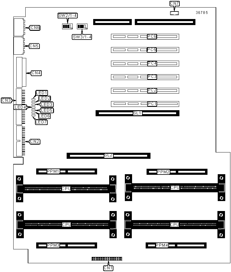
CONNECTIONS |
|||
| Purpose | Location |
Purpose | Location |
| Floppy drive interface | CN1 | PCI hot plug switch | CN7 |
| Power sensor connector | CN2 | 64-bit PCI slots | PC1 - PC6 |
| IDE interface | CN3 | Processor Power Module connectors | PPM1-PPM4 |
| Miscellaneous connector | CN4 | Peripheral board slot | SL1 |
| Power connector 1 | CN5 | Memory board slot | SL2 |
| Power connector 2 | CN6 | ||
CACHE CONFIGURATION |
| Note: 256KB/512KB cache is located on the Pentium III CPU. |
CPU SPEED SELECTION (INTEL) |
||||||
CPU speed |
Clock speed |
Multiplier |
SW2/1 |
SW2/2 | SW2/3 |
SW2/4 |
450MHz |
100MHz |
4.5x |
Off | On | Off | On |
500MHz |
100MHz |
5x |
On | On | Off | Off |
550MHz |
100MHz |
5.5x |
Off | On | Off | Off |
CPU SPEED SELECTION (INTEL CON'T) |
||||||
CPU speed |
Clock speed |
Multiplier |
SW3/1 |
SW3/2 | SW3/3 |
SW3/4 |
450MHz |
100MHz |
4.5x |
Off | On | Off | On |
500MHz |
100MHz |
5x |
On | On | Off | Off |
550MHz |
100MHz |
5.5x |
Off | On | Off | Off |
DIAGNOSTIC LED(S) |
|||
LED |
Color |
Status |
Condition |
LED1 |
Unidentified |
On |
Memory board not installed properly |
LED1 |
Unidentified | Off |
Memory board installed properly |
| LED2 | Unidentified | On |
Processor 4 not installed properly |
| LED2 | Unidentified | Off |
Processor 4 installed properly |
| LED3 | Unidentified | On |
Processor 3 not installed properly |
| LED3 | Unidentified | Off |
Processor 3 installed properly |
| LED4 | Unidentified | On |
Processor 2 not installed properly |
| LED4 | Unidentified | Off |
Processor 2 installed properly |
| LED5 | Unidentified | On |
Processor 1 not installed properly |
| LED5 | Unidentified | Off |
Processor 1 installed properly |
| LED6 | Unidentified | On |
Peripheral board not installed properly |
| LED6 | Unidentified | Off |
Peripheral board installed properly |
| LED7 | Unidentified | On |
Miscellaneous cable not installed properly |
| LED7 | Unidentified | Off |
Miscellaneous cable installed properly |
| Note: All LED's to the right of the improperly installed component's LED will be on. Only the leftmost LED is a valid indication of error. | |||
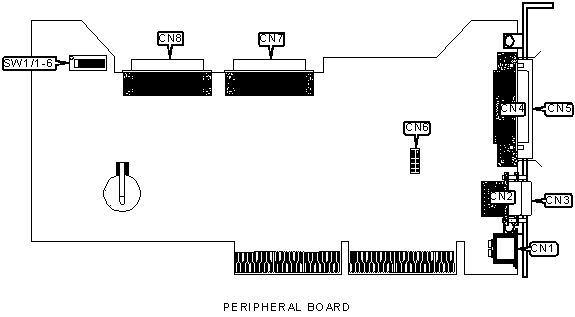
CONNECTIONS |
|||
| Purpose | Location |
Purpose | Location |
| PS/2 mouse port | CN1 | SCSI port | CN5 |
| Serial port | CN2 | Serial interface | CN6 |
| VGA port | CN3 | SCSI interface B | CN7 |
| Parallel port | CN4 | SCSI interface A | CN8 |
USER CONFIGURABLE SETTINGS |
|||
Function |
Label |
Position |
|
» |
On-board video disabled | SW1/1 | Off |
| On-board video enabled | SW1/1 | On | |
| » | Configuration lock disabled | SW1/2 | Off |
|
Configuration locked enabled | SW1/2 | On |
| » | Rack mount configuration | SW1/3 | On |
| Tower configuration | SW1/3 | Off | |
| » | Boot from diskette determined by configuration | SW1/4 | Off |
| Boot from diskette allowed | SW1/4 | On | |
| » | Boot password disabled | SW1/5 | Off |
| Boot password enabled | SW1/5 | On | |
| » | Clear configuration disabled | SW1/6 | Off |
| Clear configuration enabled | SW1/6 | On | |
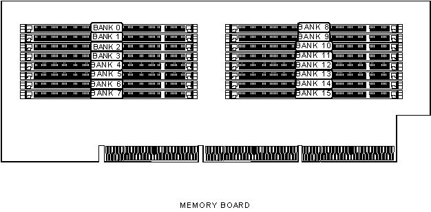
DIMM CONFIGURATION |
||||
Size |
Bank 0 |
Bank 1 |
Bank 2 |
Bank 3 |
16MB |
(1) 2M x 64 |
None |
None |
None |
32MB |
(1) 2M x 64 |
(1) 2M x 64 |
None |
None |
32MB |
(1) 4M x 64 |
None |
None |
None |
48MB |
(1) 2M x 64 |
(1) 2M x 64 |
(1) 2M x 64 |
None |
64MB |
(1) 2M x 64 |
(1) 2M x 64 |
(1) 2M x 64 |
(1) 2M x 64 |
64MB |
(1) 4M x 64 |
(1) 4M x 64 |
None |
None |
64MB |
(1) 8M x 64 |
None |
None |
None |
96MB |
(1) 4M x 64 |
(1) 4M x 64 |
(1) 4M x 64 |
None |
96MB |
(1) 4M x 64 |
(1) 4M x 64 |
(1) 2M x 64 |
(1) 2M x 64 |
128MB |
(1) 4M x 64 |
(1) 4M x 64 |
(1) 4M x 64 |
(1) 4M x 64 |
128MB |
(1) 8M x 64 |
(1) 8M x 64 |
None |
None |
128MB |
(1) 16M x 64 |
None |
None |
None |
160MB |
(1) 8M x 64 |
(1) 8M x 64 |
(1) 2M x 64 |
(1) 2M x 64 |
192MB |
(1) 8M x 64 |
(1) 8M x 64 |
(1) 8M x 64 |
None |
192MB |
(1) 8M x 64 |
(1) 8M x 64 |
(1) 4M x 64 |
(1) 4M x 64 |
256MB |
(1) 8M x 64 |
(1) 8M x 64 |
(1) 8M x 64 |
(1) 8M x 64 |
256MB |
(1) 16M x 64 |
(1) 16M x 64 |
None |
None |
256MB |
(1) 32M x 64 |
None |
None |
None |
288MB |
(1) 16M x 64 |
(1) 16M x 64 |
(1) 2M x 64 |
(1) 2M x 64 |
320MB |
(1) 16M x 64 |
(1) 16M x 64 |
(1) 4M x 64 |
(1) 4M x 64 |
384MB |
(1) 16M x 64 |
(1) 16M x 64 |
(1) 16M x 64 |
None |
384MB |
(1) 16M x 64 |
(1) 16M x 64 |
(1) 8M x 64 |
(1) 8M x 64 |
512MB |
(1) 16M x 64 |
(1) 16M x 64 |
(1) 16M x 64 |
(1) 16M x 64 |
512MB |
(1) 32M x 64 |
(1) 32M x 64 |
None |
None |
544MB |
(1) 32M x 64 |
(1) 32M x 64 |
(1) 2M x 64 |
(1) 2M x 64 |
576MB |
(1) 32M x 64 |
(1) 32M x 64 |
(1) 4M x 64 |
(1) 4M x 64 |
640MB |
(1) 32M x 64 |
(1) 32M x 64 |
(1) 8M x 64 |
(1) 8M x 64 |
768MB |
(1) 32M x 64 |
(1) 32M x 64 |
(1) 32M x 64 |
None |
768MB |
(1) 32M x 64 |
(1) 32M x 64 |
(1) 16M x 64 |
(1) 16M x 64 |
1024MB |
(1) 32M x 64 |
(1) 32M x 64 |
(1) 32M x 64 |
(1) 32M x 64 |
| Note: Board supports EDO
memory. Note: Banks 7-15 may use same configuration. If used, add additional memory to totals above for a maximum of (1024 x 4) 4096MB. |
||||
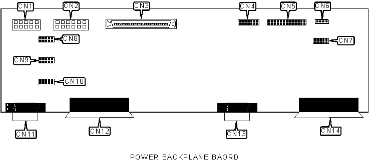
CONNECTIONS |
|||
| Purpose | Location |
Purpose | Location |
| Power connector | CN1 | Fan power connector 5 | CN8 |
| Power connector | CN2 | Fan power connector 2 | CN9 |
| Miscellaneous cable connector | CN3 | Fan power connector 1 | CN10 |
| Power switch and LED | CN4 | Redundant power supply | CN11 |
| Power sense cable connector | CN5 | Redundant power supply | CN12 |
| Power connector (CD-ROM) | CN6 | Primary power supply | CN13 |
| Fan power connectors 3 & 4 | CN7 | Primary power supply | CN14 |