DIGITAL VIEW COMPANY
SV-1024
| Card Type | Video interface controller |
| Video Chip Set | Unidentified |
| Maximum Video Memory | Unidentified |
| Video Types Supported | VGA, SVGA, XGA |
| Highest Resolution Supported | 1024 x 768 |
| Data Bus | External |
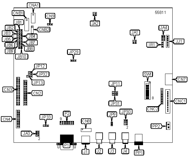
CONNECTIONS |
|||
Function |
Label |
Function |
Label |
| Panel signal connector | CN2 | IR connector | IR1 |
| Panel signal connector | CN3 | S-video in | J1 |
| Panel signal connector | CN4 | Composite video in | J2 |
| Audio board connector | CN7 | Audio in (left channel) | J3 |
| Video in interface (alternate) | CN8 | Audio in (right channel) | J4 |
| LED connector | CN9 | RS-232 serial interface | JJ1 |
| Auxiliary power out connector | CNA1 | VGA analog input port | P1 |
| Backlight inverter connector | CNB1 | VGA input interface | P2 |
| Backlight inverter connector (alternate) | CNB2 | DC power connector (main) | PP1 |
| Function controls connector | CNC1 | DC power connector (alternate) | PP2 |
| Function controls connector (alternate) | CNC2 | ||
USER CONFIGURABLE SETTINGS |
|||
Function |
Label |
Position |
|
| » | Factory configured - do not alter | JA1 | Pins 1 & 3, 2 & 4 closed |
| » | Factory configured - do not alter | JA2 | Pins 1 & 3, 2 & 4 closed |
| Panel voltage supply is +3.3V | JA3 | Pins 1 & 3, 2 & 4 closed | |
| Panel voltage supply is +5V | JA3 | Pins 3 & 5, 4 & 6 closed | |
| RS-232 voltage is +12V | JA4 | Pins 1 & 3, 2 & 4 closed | |
| RS-232 voltage is +5V | JA4 | Pins 3 & 5, 4 & 6 closed | |
| » | Factory configured - do not alter | JB1 | Unidentified |
| Backlight inverter on/off control signal high = CCFT ON | JB3 | Pins 1 & 2 closed | |
| Backlight inverter on/off control signal low = CCFT ON | JB3 | Pins 2 & 3 closed | |
| » | Factory configured - do not alter | JB4 | Open |
| » | Factory configured - do not alter | JB5 | Open |
| » | Factory configured - do not alter | JB6 | Pins 1 & 2 closed |
| » | Factory configured - do not alter | JB7 | Pins 1 & 2 closed |
| » | Factory configured - do not alter | JB8 | Pins 1 & 2 closed |
| Backlight inverter status is active low | JB9 | Pins 1 & 2 closed | |
| Backlight inverter status is active high | JB9 | Pins 2 & 3 closed | |
| » | Factory configured - do not alter | JB10 | Open |
| » | Factory configured - do not alter | JP9 | Open |
| » | Factory configured - do not alter | JP11 | Pins 2 & 3 closed |
| +12V safe panel power enabled | JP12 | Closed | |
| +12V safe panel power disabled | JP12 | Open | |
| Clock panel is single pixel | JP13 | Pins 1 & 2 closed | |
| Clock panel is double pixel | JP13 | Pins 2 & 3 closed | |
| » | Factory configured - do not alter | JP29 | Pins 2 & 3 closed |
| » | Factory configured - do not alter | JP30 | Pins 1 & 3, 2 & 4 closed |
| » | Factory configured - do not alter | JP31 | Pins 2 & 3 closed |
| » | Factory configured - do not alter | JP32 | Closed |
| » | Factory configured - do not alter | JP33 | Pins 1 & 2 closed |
| Dot clock display is inverted by 180 degrees | SW1/1 | Unidentified | |
| Clock panel is single pixel | SW1/2 | On | |
| Clock panel is double pixel | SW1/2 | Off | |
| » | Factory configured - do not alter | SW1/3 | Off |
| Volume control enabled | SW1/4 | On | |
| Volume control disabled | SW1/4 | Off | |
| » | Factory configured - do not alter | SW1/5 | Off |
| » | Factory configured - do not alter | SW1/6 | Off |
| » | Factory configured - do not alter | SW1/7 | Off |
| » | Factory configured - do not alter | SW1/8 | Off |
| Note: Setting of JB9 is dependant of JB3 setting. | |||
BACKLIGHT INVERTER VOLTAGE SELECTION |
|
Backlight inverter on/off control signal |
JB2 |
| High = +12V | Pins 1 & 2 closed |
| High = +5V | Pins 2 & 3 closed |
| High = Open collector | Open |
| Note: Settings for JB2 is dependant of the inverter used. | |
MISCELLANEOUS TECHNICAL NOTES |
This video controller is for use with LCD and flat panel display applications.Settings can be controlled by an analog VR or digital function control device. |