DIGITAL VIEW COMPANY
MAV-N32
| Card Type | Video card |
| Video Chip Set | Unidentified |
| Maximum Video Memory | Unidentified |
| Video Types Supported | Unidentified |
| Highest Resolution Supported | 320 x 240 |
| Data Bus | None |
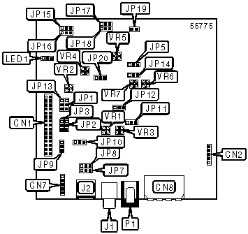
CONNECTIONS |
|||
Function |
Label |
Function |
Label |
| Panel connector | CN1 | Composite video connector | J1 |
| Switch connector | CN2 | S-video connector | J2 |
| Video connector | CN7 | LED connector | LED1 |
| Power connector | CN8 | DC power connector | P1 |
USER CONFIGURABLE SETTINGS |
|||
Function |
Label |
Position |
|
| » | Factory configured - do not alter | JP1 | Pins 2 & 3 closed |
| Image orientation control normal vertical | JP2 | Pins 1 & 2 closed | |
| Image orientation control mirrored vertical | JP2 | Pins 2 & 3 closed | |
| Image orientation control normal horizontal | JP3 | Pins 1 & 2 closed | |
| Image orientation control mirrored horizontal | JP3 | Pins 2 & 3 closed | |
| Internal VR selected | JP5 | Pins 1 & 2 closed | |
| External VR selected | JP5 | Pins 2 & 3 closed | |
| PAL video system selected | JP9 | Pins 1 & 2 closed | |
| NTSC video system selected | JP9 | Pins 2 & 3 closed | |
| » | Factory configured - do not alter | JP14 | Pins 1 & 2 closed |
| » | Factory configured - do not alter | JP15 | Pins 1 & 2 closed |
| » | Factory configured - do not alter | JP16 | Pins 1 & 2 closed |
| » | Factory configured - do not alter | JP17 | Pins 1 & 2 closed |
| » | Factory configured - do not alter | JP18 | Pins 1 & 2 closed |
| » | Factory configured - do not alter | JP19 | Pins 1 & 2 closed |
V IDEO SOURCE SELECTION |
||
Setting |
JP7 | JP8 |
| Composite video in | Pins 1 & 2 closed | Pins 1 & 2 closed |
S -video in |
Pins 2 & 3 closed | Pins 2 & 3 closed |
V IDEO SYSTEM / SOURCE SELECTION |
||||
| Settings | JP10 | JP11 | J P12 |
JP13 |
| Composite PAL | P ins 1 & 2 closed |
Pins 1 & 2 closed | Pins 1 & 2 closed | Pins 1 & 2 closed |
| Composite NTSC | Pins 2 & 3 closed | Pins 2 & 3 closed | Pins 2 & 3 closed | Pins 2 & 3 closed |
| S-video | O pen |
Open | Open | Open |
V R CONTROLS |
|||
Function |
Label |
Function |
Label |
| Color | VR1 | Backlight brightness | VR5 |
| Contrast | VR2 | Reserved | VR6 |
| Tint | VR3 | Reserved | VR7 |
| Panel brightness | VR4 | ||
| Note: VR controls are used to adjust the indicated image function levels. | |||