AMPRO COMPUTERS, INC.
MINIMODULE/VFP-II
| Card Type | Video controller |
| Video Chip Set | Chips & Technologies |
| Maximum Video Memory | 1MB DRAM |
| Video Types Supported | CGA, EGA, Monochrome, SVGA, VGA |
| Highest Resolution Supported | 1280 x 1024 |
| I/O Options | External video overlay connector, flat panel connector, CRT VGA connector |
| Data Bus | PC/104 (16-bit) |
CONNECTIONS |
|||
Function |
Label |
Function |
Label |
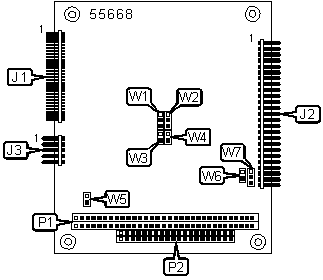
| 60-pin external video overlay connector | J1 | PC/104 connector (8-bit) | P1 |
| 50-pin flat panel connector | J2 | PC/104 connector (16-bit) | P2 |
| 10-pin CRT VGA connector | J3 | ||
USER CONFIGURABLE SETTINGS |
|||
Function |
Label |
Position |
|
| » | Shift clock high-to-low transition | W2 | Pins 1 & 2 closed |
| Shift clock low-to-high transition | W2 | Pins 2 & 3 closed | |
| » | Video BIOS flash memory is write protected | W3 | Open |
| Video BIOS flash memory is non-write protected | W3 | Closed | |
| » | Video BIOS normal operation | W4 | Open |
| Video BIOS disabled | W4 | Closed | |
| » | IRQ2/IRQ9 available on bus | W5 | Open |
| Video interrupt connected to IRQ2/IRQ9 | W5 | Closed | |
| » | Onboard contrast control connected to Vee supply | W6 | Closed |
| Onboard contrast control disconnected | W6 | Open | |
| » | Vee polarity is negative (-15V to -35V) | W7 | Pins 1 & 2 closed |
| Vee polarity is positive (+15V to +35V) | W7 | Pins 2 & 3 closed | |
| Note: Set Vee polarity and voltage before connecting the LCD panel so that damage will not occur. | |||
FLATPANEL POWER SIGNAL SELECTION |
||
Setting |
W1 |
|
| » | Backlight signal enabled | Pins 1 & 2 closed |
| Vee signal enabled | Pins 2 & 3 closed | |
| Backlight signal disabled | Open | |
| Note: W1 has a dual use pin. If 24-bit PC-video is used, the dual pin becomes an input rather than a flatpanel signal selector. In this case, the jumper should be removed or set to pins 2 & 3. | ||
MISCELLANEOUS TECHNICAL NOTES |
The MiniModule/VFP-II can be installed as part of an Ampro CoreModule stack, Ampro Little Board CPU, or PC/104-compatible module. Analog monitors with a 15-pin or 9-pin interface can be attached to the CRT (J3) connector with an adapter (10-wire flat ribbon cable to a DB9S D-Sub or DB15S D-Sub connector). Blurred video may occur if ribbon cable used with the CRT (J3) connector is non shielded and longer than 24 inches. The flat panel connector does not share a standardized interface pin configuration and therefor may not be readily compatible with other devices. |