PERITEK CORPORATION
VCL-P
| Card Type | Video card |
| Video Chip Set | Texas Instruments |
| Maximum Video Memory | 32MB DRAM |
| Video Types Supported | VGA |
| Highest Resolution Supported | 1600 x 1280 (analog), 1280 x 1024 (digital) |
| Data Bus | 32-bit PCI |
CONNECTIONS |
|||
Function |
Label |
Function |
Label |
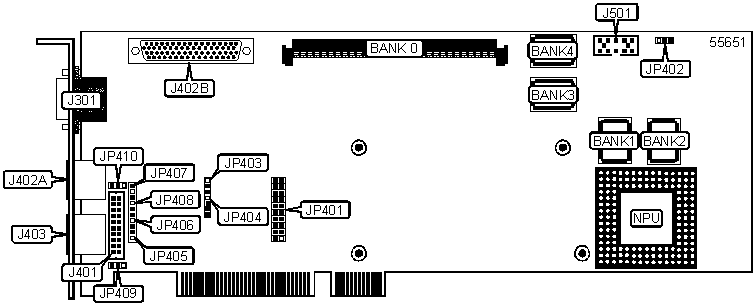
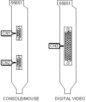
| S/B DB-9 RS-232 connector A | CN1 | PS/2 connector A | J402A |
| S/B DB-9 RS-232 connector B | CN2 | 68-pin header to digital video output connector | J402B |
| 68-pin mini-DIN digital video connector | CN3 | PS/2 connector B | J403 |
| 15-pin analog video port (DB-22) | J301 | Unidentified | J501 |
| 20-pin header to (2) DB-9 serial connectors | J401 | ||
USER CONFIGURABLE SETTINGS |
|||
Function |
Label |
Position |
|
| » | Factory configured - do not alter | JP401/Pins 1 & 2 | Unidentified |
| » | 28F020 EEPROM programming disabled | JP402 | Pins 2 & 3 open |
| 28F020 EEPROM programming enabled | JP402 | Pins 2 & 3 closed | |
| AutoBoot enabled | JP401 | Pins 19 & 20 closed | |
| AutoBoot disabled | JP401 | Pins 19 & 20 open | |
| Note: 28F020 EEPROM
programming only. Remove jumper when programming is complete. Note: AutoBoot jumper should not be installed unless autobooting EEPROMS are installed |
|||
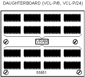
NON-DISPLAY DRAM CONFIGURATION |
|
Size |
Bank 0 |
0MB |
None |
4MB |
1MB x 32 (72pin SIMM) |
16MB |
4MB x 32 (72pin SIMM) |
32MB |
8MB x 32 (72pin SIMM) |
DEFAULT INITIALIZATION TABLE SELECTION |
|||||
Table Number |
Table Name | Screen Dimensions | JP401/Pins 9 & 10 | JP401/Pins 11 & 12 | JP401/Pins 15 & 16 |
| 0 | L*VX168.ibm | 1600 x 1280 | Open | Open | Closed |
| 1 | L*VX128.ibm | 1280 x 1024 | Closed | Open | Closed |
| 2 | L*VX108.ibm | 1024 x 768 | Open | Closed | Closed |
| 3 | L*VVGA8.ibm | 640 x 480 | Closed | Closed | Closed |
| 4-7 | Serial EEPROM tables | Custom | Closed/Open | Closed/Open | Open |
Note: When JP401-pins 15 & 16 are open, PTERM checks for tables in Serial EEPROM. When JP401-pins 15 & 16 are closed, PTERM uses the table specified in Flash EEPROM. (* = 1 for VCL/8, 5 for VCL/24) |
|||||
PTERM SCREEN SIZE SELECTION |
|
Size |
JP401/Pins 13 & 14 |
80 characters x 24 lines |
Open |
Full screen |
Closed |
| Note: Rows and columns dimensions are set by the initialization table. When the RTS function is enabled but not connected, PTERM will not transmit. | |
FLASH EEPROM MEMORY CONFIGURATION |
||||
Size |
Bank 1 |
Bank 2 |
Bank 3 |
Bank 4 |
512K |
512KB x 32 |
None |
None |
None |
| 1MB | 512KB x 32 | 512KB x 32 | None | None |
| 1.5MB | 512KB x 32 | 512KB x 32 | 512KB x 32 | None |
| 2MB | 512KB x 32 | 512KB x 32 | 512KB x 32 | 512KB x 32 |
Note: Acceptable devices include AM28F020-150JC (for 1 MB total) and AM29F040-150JC (for 2 MB total). |
||||
FLASH EEPROM JUMPER SELECTION |
|
Configuration |
JP402/Pins 1 & 2 |
| Using AM29F040 chips | Closed |
| Not using AM29F040 chips | Open |
SERIAL MODE SELECTION |
|
Setting |
JP401/Pins 3 & 4 |
8 bits/No parity |
Open |
7 bits/Even parity |
Closed |
XON/XOFF SELECTION |
|
Setting |
JP401/Pins 5 & 6 |
Disabled |
Open |
Enabled |
Closed |
RTS/CTS SELECTION |
|
Setting |
JP401/Pins 7 & 8 |
Disabled |
Open |
Enabled |
Closed |
Note: The secondary pointer port is available only if RTS/CTS is disabled. |
|
DIAGNOSTIC LED(S) |
|||
LED |
Color |
Status |
Condition |
| Unidentified | Red |
1 blink |
Board was not initialized |
| Unidentified | Red | 2 blinks |
Board type was not determined by board side code |
| Unidentified | Red | 3 blinks |
Pixel size value is other then 8 or 24 |
| Unidentified | Red | 4 blinks | Incorrect pixel for board configuration |
| Unidentified | Red | 5 blinks | Video width is unidentified |
| Unidentified | Red | 6 blinks | Mismatch of video width and Video Wide information from initialization table |
| Unidentified | Red | 7 blinks | Display size is too big |
| Unidentified | Red | 8 blinks | Mismatch of initialization table and board type |
| Unidentified | Red | 9 blinks | Mismatch of initialization table and colormap type |
| Unidentified | Red | 11 blinks | Initialization state is bad |
| Unidentified | Red | >16 blinks | IBM561 software error |
| Unidentified | Green | On | Pass |
| Unidentified | Red | On | Fail |
CONSOLE PORT CONNECTOR PIN OPTION |
|||
Setting |
Location |
Position |
|
| » | Pin 8 to Console (Port 2) RTS | JP403 | Pins 1 & 2 closed |
| Pin 8 to Secondary Pointer (Port 3) TX | JP403 | Pins 2 & 3 closed | |
| » | Pin 7 to Console (Port2) CTS | JP404 | Pins 1 & 2 closed |
| Pin 7 to Secondary Pointer (Port 3) RX | JP404 | Pins 2 & 3 closed | |
| Pin 9 to fused (.5A) +12 volts | JP410 | Pins 1 & 2 closed | |
| Pin 9 to fused (.5A) +5 volts | JP410 | Pins 2 & 3 closed | |
MOUSE PORT (PORT 0 AND PORT 1) CONNECTOR PIN OPTION |
|||
Setting |
Location |
Position |
|
| » | Pin 3 to -12V | JP405 | Pins 1 & 2 closed |
| Pin 3 to Port 0 TX | JP405 | Pins 2 & 3 closed | |
| Pin 4 to fused (.5A) +5 volts | JP406 | Pins 1 & 2 closed | |
| Pin 6 to LK401 (Port 1) RX | JP407 | Pins 1 & 2 closed | |
| Pin 8 to LK401 (Port 1) TX | JP408 | Pins 1 & 2 closed | |
| Pin 9 to fused (.5A) +12 volts | JP409 | Pins 1 & 2 closed | |
| Pin 9 to fused (.5A) +5 volts | JP409 | Pins 2 & 3 closed | |
| Note: Pins 3, 4 and 7 should not exceed 10 mA of current draw. | |||