PARADYNE CORPORATION
ACCULINK 3163 DSU/CSU
| Device Type | Digital I/O |
| I/O Options | T1 network interface, modem connector, DTE port, COM port interface |
| Maximum Modem Rate | 2400bps |
| Data Modulation Protocol | V.22bis |
| Wiring Type | Unshielded twisted pair |
| Link Layer Protocols | Point-to Point (PPP), Serial Line Internet (SLIP) |
CONNECTIONS |
|||
Function |
Label |
Function |
Label |
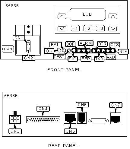
| Test jack - line in | CN1 |
Communication port | CN 5 |
| Test jack - line out | CN2 |
Modem port via RJ-11 | CN 6 |
| Power connector | CN 3 |
T1 network interface via RJ-48 | CN 7 |
| DTE port via DB-25 | CN 4 |
||
| Note:
Network monitor-in monitors the signal going into the network, where as network
monitor-out monitors the signal going out of the network. Note: Do not connect COM port or AUX port to PSTN or T1 network. |
|||
DIAGNOSTIC LED(S) |
|||
LED |
Color |
Status |
Condition |
OK |
Green |
On |
DSU/CSU power is on |
OK |
Green |
Off |
DSU/CSU power is off or detecting a system failure |
OK |
Green |
Blinking |
DSU/CSU is downloading software |
Fail |
Yellow |
On |
Error has been detected on network |
Fail |
Yellow |
Off |
Error has not been detected on network |
Fail |
Yellow |
Blinking |
DSU/CSU is conducting a self test |
Test |
Yellow |
On |
DSU/CSU is executing a test |
Test |
Yellow |
Off |
DSU/CSU is not executing a test |
SIG |
Green |
On |
DSU/CSU is receiving a recoverable signal from network |
SIG |
Green |
Off |
DSU/CSU cannot recover the signal from network |
OOF |
Yellow |
On |
Out of frame condition detected on network |
OOF |
Yellow |
Off |
Out of frame condition not detected on network |
Alrm |
Yellow |
On |
Alarm condition detected on network |
Alrm |
Yellow |
Off |
Alarm condition not detected on network |
EER |
Yellow |
On |
Excessive error rate exceeded on network |
EER |
Yellow |
Off |
Excessive error rate not exceeded on network |
| DTR | Green | On | DTR signal is high |
| DTR | Green | Off | DTR signal is low |
| TXD | Yellow | On | Receiving all ones from the DTE |
| TXD | Yellow | Off | Receiving all zeros from the DTE |
| TXD | Yellow | Blinking | Data is being transferred |
| RXD | Yellow | On | Transmitting all ones to the DTE |
| RXD | Yellow | Off | Transmitting all zeros to the DTE |
| RXD | Yellow | Blinking | Data is being transferred |
| CTS | Yellow | On | CTS signal is high |
| CTS | Yellow | Off | CTS signal is low |
| RTS | Yellow | On | RTS signal is high |
| RTS | Yellow | Off | RTS signal is low |
| Note: Alarm types (LOS, LOF, EER, Yellow, AIS) can be determined with use of the Device Health and Status command. Note: EER LED is valid only when ESF framing is being used. |
|||
MISCELLANEOUS TECHNICAL NOTES |
Note: Using Front Panel Emulation, a graphical representation of the LCD front panel can be displayed on an attached PC. |