AM5614IVSP-HY
| Card Type | Modem |
| Chip Set | Unidentified |
| Maximum Modem Rate | 56Kbps |
| Maximum Fax Rate | 14.4Kbps |
| Data Modulation Protocol | Bell 103A/212 ITU-T V.21, V.22, V.22bis, V.23, V.32, V.32bis, V.34, K56Flex |
| Fax Modulation Protocol | ITU-T V.17, V.27ter, V.29, T.30, T.4 |
| Error Correction/Compression | MNP5, V.42, V.42bis |
| Fax Class | Class 3 |
| Data Bus | 16-bit ISA |
| Card Size | Three-quarter length, full-height card |
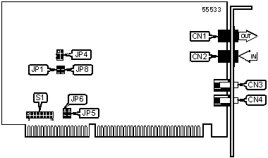
CONNECTIONS |
|||
Function |
Label |
Function |
Label |
| Line out | CN1 |
Speaker connector | CN3 |
| Line in | CN2 |
Microphone connector | CN4 |
USER CONFIGURABLE SETTINGS |
||
Setting |
Label |
Position |
| » Factory configured - do not alter | JP1 |
Open |
INTERRUPT/SERIAL PORT ADDRESS |
||||||
COM |
IRQ |
S1 |
JP4 |
JP5 |
JP6 |
JP8 |
COM1 |
4 |
3 & 4, 5 & 6, 7 & 8 |
1 & 2 |
1 & 2 |
1 & 2 |
Open |
COM2 |
3 |
3 & 4, 9 & 10, 11 & 12 |
1 & 2 |
1 & 2 |
1 & 2 |
Open |
COM3 |
4 |
1 & 2, 5 & 6, 7 & 8 |
1 & 2 |
1 & 2 |
1 & 2 |
Open |
COM4 |
3 |
1 & 2, 9 & 10, 11 & 12 |
1 & 2 |
1 & 2 |
1 & 2 |
Open |
| Note: Indicated pins are in the closed position. | ||||||
PLUG AND PLAY SELECTION |
||||
Setting |
JP4 |
JP5 |
JP6 |
JP8 |
Enable Plug and Play |
Pins 2 & 3 closed |
Pins 2 & 3 closed |
Pins 2 & 3 closed |
Closed |
MISCELLANEOUS TECHNICAL NOTES |
The actual locations of JP4, JP5, JP6 and JP8 may differ from those indicated. |
SUPPORTED COMMAND SET |
Basic AT Commands |
| AT, ‘+++’, A/ |
| A, B, C, E, H, M, O, P, Q, T, V, W, X, Y, Z |
| &C, &D, &P, &S, &V, &W, &Y, &Z |
Extended AT Commands |
| \A, \B, \G, \K, \N, \V |
| %C, %L, %Q |
S Registers |
| S0, S1, S2, S3, S4, S6, S8, S9, S10, S11, S12, S18, S24, S25, S26, S29, |
| S38, S91, S92, S95 |
Special Commands |
| *H, -K, -Q, )M, #CID, +MS? |
| Note: See MHI Help File for full command documentation. |
Proprietary AT Command Set
AUTO-MODE DETECTION |
|
| Type: | Configuration |
| Format: | AT [cmds] Nn [cmds] |
| Description: | Selects the automatic detection. |
Command |
Function |
N0 |
Auto-mode detection disabled |
N1 |
Auto-mode detection enabled |
COMMUNICATIONS MODE |
|
| Type: | Configuration |
| Format: | AT [cmds] &Mn [cmds] |
| Description: | Selects communications mode - same at &Q0 |
Command |
Mode |
&M0 |
Asynchronous mode |
COMMUNICATIONS MODE |
|
| Type: | Configuration |
| Format: | AT [cmds] &Qn [cmds] |
| Description: | Selects communications mode options |
Command |
Mode |
&Q0 |
Asynchronous mode, serial port speed follows connect speed. |
&Q5 |
Attempts error correction mode; fallback to asynchronous mode |
&Q6 |
Buffered asynchronous mode |
DATA SET READY (DSR) |
|
| Type: | Configuration |
| Format: | AT [cmds] &Sn [cmds] |
| Description: | Selects DSR options |
Command |
Function |
&S0 |
DSR forced high |
&S1 |
DSR high only while modem is connected |
DIAL |
|
| Type: | Immediate |
| Format: | AT [cmds] D<#> [cmds] |
| Description: | Dials telephone number according to any modifiers included in the string |
| Note: | Any combination of modifiers can be used to produce the desired dial functions in sequence. |
Command |
Function |
DJ |
Attempt MNP 10 negotiation at 1200bps during current call attempt |
DK |
Enables power level adjustment during MNP 10 negotiation during current call attempt |
DL |
Re-dial last number |
DP |
Pulse dialing enabled |
DS=n |
Dial stored telephone number n |
DT |
Tone dialing enabled/Pulse dialing disabled |
DW |
Dialing resumed following dial tone detection |
D, |
Dialing paused for amount of time specified in S8 register |
D! |
Flash function initiated. Modem commanded to go off-hook for specified time before returning on-hook. |
D@ |
Wait for Quite Answer function enabled. Modem waits until a "quiet answer," a ring-back signal followed by silence up to the time specified in S7, is received prior to executing the rest of the dial string. |
D; |
Modem returned to idle state after dialing. The semicolon can only be placed at the end of the dial command. |
D^ |
Toggles tone and pulse dialing for current call attempt |
FACTORY DEFAULT PROFILE |
|
| Type: | Configuration |
| Format: | AT [cmds] &Fn [cmds] |
| Description: | Sets values in active profile to values found in the default profile |
Command |
Function |
&F0 |
Resets modem to factory profile 0 |
&F1 |
Resets modem to factory profile 1 |
FLOW CONTROL |
|
| Type: | Configuration |
| Format: | AT [cmds] &Kn [cmds] |
| Description: | Enables flow control options |
Command |
Function |
&K0 |
Flow control disabled |
&K3 |
RTS/CTS flow control enabled |
&K4 |
XON/XOFF flow control enabled |
&K5 |
Transparent XON/XOFF flow control enabled |
&K6 |
Unidirectional XON/XOFF flow control enabled |
GUARD TONE |
|
| Type: | Configuration |
| Format: | AT [cmds] &Gn [cmds] |
| Description: | Commands the modem to transmit a guard tone in V.22/V.22bis |
| Note: | Used primarily for international data transmission |
Command |
Function |
&G0 |
Guard tone disabled |
&G1 |
Guard tone disabled |
&G2 |
1800Hz guard tone enabled |
REPORT INFORMATION |
|
| Type: | Immediate |
| Format: | AT [cmds] In [cmds] |
| Description: | Displays information requested |
Command |
Function |
I1 |
Reports ROM checksum |
I2 |
Reports ERROR |
I3 |
Reports firmware version number |
I4 |
Reports OEM identifier string |
I5 |
Reports country code information |
I6 |
Reports modem data pump model number and internal code version |
I7 |
Reports DAA code |
SPEAKER VOLUME |
||
| Type: | Configuration | |
| Format: | AT [cmds] Ln [cmds] | |
| Description: | Controls speaker volume | |
Command |
Function |
|
L0 |
Low volume setting | |
| » | L1 |
Low volume setting |
L2 |
Medium volume setting | |
L3 |
Highest volume setting | |
TEST MODES |
|
| Type: | Immediate |
| Format: | AT [cmds] &Tn |
| Description: | Selects test options |
Command |
Function |
&T0 |
End current test |
&T1 |
Begin local analog loopback test |
&T8 |
Begin local analog loopback and self-test |
Extended AT Command Set
AUTO-RETRAIN - AUTO-FALLBACK/FALL-FORWARD |
|
| Type: | Configuration |
| Format: | AT [cmds] %En [cmds] |
| Description: | Controls auto-retrain mode and fallback/fall-forward |
Command |
Function |
%E0 |
Auto-retrain disabled |
%E1 |
Auto-retrain enabled |
%E2 |
Auto-fallback/fall-forward enabled |
%E3 |
Auto-retrain and line quality monitor enabled; enables fast hang-up |
Special AT Command Set
MODULATION SELECTION |
|
| Type: | Configuration |
| Format: | AT [cmds] +MS=x,y,z,a,b,c [cmds] |
| Description: | Sets options for active protocol and connection rates (the transfer rates specified by z and a must be valid for the protocol selected), auto-mode, robbed bit signaling generation or detection and u-Low or A-Low codec type. |
Command |
Function |
x=0 |
V.21 |
x=1 |
V.22 |
x=2 |
V.22bis |
x=3 |
V.23 |
x=9 |
V.32 |
x=10 |
V.32bis |
x=11 |
V.34 |
x=56 |
K56flex |
x=64 |
Bell 103 |
x=69 |
Bell 212A |
y=0 |
Automode disabled |
y=1 |
Automode with V.8bis/V.8 or V.32 protocol enabled |
z, a=300 |
Set minimum or maximum transfer rate at 300bps, respectively. |
z, a=1200 |
Set minimum or maximum transfer rate at 1200bps, respectively. |
z, a=2400 |
Set minimum or maximum transfer rate at 2400bps, respectively. |
z, a=4800 |
Set minimum or maximum transfer rate at 4800bps, respectively. |
z, a=7200 |
Set minimum or maximum transfer rate at 7200bps, respectively. |
z, a=9600 |
Set minimum or maximum transfer rate at 9600bps, respectively. |
z, a=12000 |
Set minimum or maximum transfer rate at 12000bps, respectively. |
z, a=14400 |
Set minimum or maximum transfer rate at 14400bps, respectively. |
z, a=16800 |
Set minimum or maximum transfer rate at 16800bps, respectively. |
z, a=19200 |
Set minimum or maximum transfer rate at 19200bps, respectively. |
z, a=21600 |
Set minimum or maximum transfer rate at 21600bps, respectively. |
z, a=24000 |
Set minimum or maximum transfer rate at 24000bps, respectively. |
z, a=26400 |
Set minimum or maximum transfer rate at 26400bps, respectively. |
z, a=28800 |
Set minimum or maximum transfer rate at 28800bps, respectively. |
z, a=31200 |
Set minimum or maximum transfer rate at 31200bps, respectively. |
z, a=33600 |
Set minimum or maximum transfer rate at 33600bps, respectively. |
z, a=36000 |
Set minimum or maximum transfer rate at 36000bps, respectively. |
z, a=38000 |
Set minimum or maximum transfer rate at 38000bps, respectively. |
z, a=40000 |
Set minimum or maximum transfer rate at 40000bps, respectively. |
z, a=42000 |
Set minimum or maximum transfer rate at 42000bps, respectively. |
z, a=44000 |
Set minimum or maximum transfer rate at 44000bps, respectively. |
z, a=46000 |
Set minimum or maximum transfer rate at 46000bps, respectively. |
z, a=48000 |
Set minimum or maximum transfer rate at 48000bps, respectively. |
z, a=50000 |
Set minimum or maximum transfer rate at 50000bps, respectively. |
z, a=52000 |
Set minimum or maximum transfer rate at 52000bps, respectively. |
z, a=54000 |
Set minimum or maximum transfer rate at 54000bps, respectively. |
z, a=56000 |
Set minimum or maximum transfer rate at 56000bps, respectively. |
b=0 |
Sets codec type to m-Law |
b=1 |
Sets codec type to A-Law |
c=0 |
Robbed bit signaling generation/detection disabled |
c=1 |
Robbed bit signaling generation/detection enabled |
S(status) Registers
BACKSPACE CHARACTER |
|
| Type: | Register |
| Format | AT [cmds] S5=n [cmds] |
| Range: | 0-32 |
| Unit: | ASCII |
| Description: | Selects a character used for backspace <BS> |
BIT-MAPPED REGISTER S14 |
||
| Format: | AT [cmds] S14=n [cmds] | |
| Range: | 0-174 | |
| Unit: | Bit-mapped | |
| Description: | Controls echo, result codes and display, dial mode, and answer/originate mode. | |
Bit |
Value |
Function |
0 |
0 |
Not used |
1 |
0 1 |
Command echo disabled Command echo enabled |
2 |
0 1 |
Result codes enabled Result codes disabled |
3 |
0 1 |
Display result codes in
numeric format Display result codes in verbose format |
4 |
0 |
Not used |
5 |
0 1 |
Tone dial enabled Pulse dial enabled |
6 |
0 |
Not used |
7 |
0 1 |
Answer mode enabled Originate mode enabled |
BIT-MAPPED REGISTER S21 |
||
| Format | AT [cmds] S21=n [cmds] | |
| Range: | 0-253 | |
| Unit: | Bit-mapped | |
| Description: | Selects jack type, CTS/DCD/DSR signals, low DTR action, and the long space disconnect function. | |
Bit |
Value |
Function |
0 |
0 1 |
Selects RJ-11, RJ-41S, or
RJ45S jack Selects RJ-12 or RJ-13 jack |
1 |
0 |
Not used |
2 |
0 1 |
CTS follows RTS CTS forced high |
4, 3 |
00 01 10 11 |
DTR signal ignored Modem goes to command mode on low DTR Modem disconnects on low DTR; Auto-Answer is disabled. Modem is initialized on low DTR |
5 |
0 1 |
DCD forced high DCD normal |
6 |
0 1 |
DSR forced high DSR normal |
7 |
0 1 |
Long space disconnect
function disabled Long space disconnect function enabled |
BIT-MAPPED REGISTER S22 |
||
| Format | AT [cmds] S22=n [cmds] | |
| Range: | 0-255 | |
| Unit: | Bit-mapped | |
| Description: | Controls speaker volume and controls, limits results codes, and pulse dial make/break ratio. | |
Bit |
Value |
Function |
1, 0 |
00 01 10 11 |
Low level volume Low level volume Medium level volume High level volume |
3, 2 |
00 01 10 11 |
Speaker off Speaker off on carrier Speaker always on Speaker on during handshake |
6 - 4 |
000 100 101 110 111 |
Basic result codes only
enabled Basic and connection speed result codes enabled Basic and connection speed result codes and dial tone detection enabled All result codes except dial tone detection enabled All result codes enabled |
7 |
0 |
Not used |
BIT-MAPPED REGISTER S23 |
||
| Format | AT [cmds] S23=n [cmds] | |
| Range: | 0-189 | |
| Unit: | Bit-mapped | |
| Description: | Grants/denies remote digital loopback, controls DTE rate and parity, and sets guard tone. | |
Bit |
Value |
Function |
0 |
0 1 |
Remote digital loopback
denied Remote digital loopback allowed |
3 - 1 |
000 001 010 011 100 101 110 111 |
Sets serial port speed to
0-300bps Sets serial port speed to 600bps Sets serial port speed to 1200bps Sets serial port speed to 2400bps Sets serial port speed to 4800bps Sets serial port speed to 9600bps Sets serial port speed to 19200bps Sets serial port speed to 38400bps or higher |
5, 4 |
00 01 10 11 |
Parity even Space Parity Parity odd Mark or No Parity |
7, 6 |
00 01 10 |
Guard tone disabled Guard tone disabled Guard tone 1800Hz enabled |
BIT-MAPPED REGISTER S28 |
||
| Format | AT [cmds] S28=n [cmds] | |
| Range: | 0-31 | |
| Unit: | Bit-mapped | |
| Description: | Controls V.23 split speed and transmit/receive speed. | |
Bit |
Value |
Function |
0 |
0 |
Not used |
1 |
0 |
Not used |
2 |
0 |
Not used |
4, 3 |
00 01 10 11 |
39ms make/61ms break at
10pps 33ms make/67ms break at 10pps 39ms make/61ms break at 20pps 33ms make/67ms break at 20pps |
5 |
0 |
Not used |
6, 7 |
00 01 10 |
Link negotiated at highest
speed Link negotiated at 1200bps Link negotiated at 4800bps |
BIT-MAPPED REGISTER S31 |
||
| Format: | AT [cmds] S31=n [cmds] | |
| Range: | 0-10 | |
| Description: | Select automode and extended result code format. | |
Bit |
Value |
Function |
0 |
0 |
Not used |
1 |
0 1 |
Auto-mode detection
disabled Auto-mode detection enabled |
3, 2 |
00 01 10 |
Enables CONNECT result
codes to report DTE speed Full reporting of CONNECT result codes Enables CONNECT result codes to report DCE speed |
BIT-MAPPED REGISTER S40 |
||
| Format: | AT [cmds] S40=n [cmds] | |
| Range: | 0-255 | |
| Unit: | Bit-mapped | |
| Description: | Controls power level and break handling; selects MNP extended services, link negotiation, and block size. | |
Bit |
Value |
Function |
0, 1 |
00 01 10 |
MNP Extended Services
disabled MNP Extended Services enabled MNP Extended Servcies enabled without indicating MNP during answer detection phase |
2 |
0 1 |
Enable power level
auto-adjust for cellular use Enable forced power level for cellular use |
5, 4, 3 |
000 001 010 011 100 101 |
AT\K0 AT\K1 AT\K2 AT\K3 AT\K4 AT\K5 |
7, 6 |
00 01 10 11 |
MNP block size is 64
characters MNP block size is 128 characters MNP block size is 192 characters MNP block size is 256 characters |
BIT-MAPPED REGISTER S41 |
||
| Format: | AT [cmds] S41=n [cmds] | |
| Range: | 0-31 | |
| Unit: | Bit-mapped | |
| Description: | Selects compression, auto-retrain, flow control, and MNP mode. | |
Bit |
Value |
Function |
1 - 0 |
00 01 10 11 |
Data compression disabled MNP5 enabled V.42bis enabled MNP5 and V.42bis enabled |
6, 2 |
00 01 10 |
Retrain disabled Retrain enabled Fallback/fall forward enabled |
3 |
0 1 |
Flow control disabled Flow control enabled |
4 |
0 1 |
Stream mode for MNP Block mode for MNP |
5 |
0 |
Not Used |
7 |
0 1 |
Fallback to V.22bis/V.22
disabled Fallback to V.22bis/V.22 enabled |
BREAK OPTIONS |
|
| Type: | Register |
| Format: | AT [cmds] S82=n [cmds] |
| Description: | Use for compatibiltiy only. Changing values in this register will have no affect on modem functions. |
CONNECTION FAILURE CODES |
|
| Type: | Register |
| Format | AT [cmds] S86? [cmds] |
| Description: | Reports codes which correspond to the possible causes of a connection failure |
Value |
Meaning |
0 |
Normal hang up |
4 |
Carrier signal lost |
5 |
No error-control detected for remote modem during feature negotiation |
9 |
No common protocol found |
12 |
No failure - remote modem disconnected normally |
13 |
Remote modem failed to respond after 10 re-transmissions same message |
14 |
Violation of negotiated protocol caused failure |
DCE LINE SPEED |
|
| Type: | Register |
| Format: | AT [cmds] S37=n [cmds] |
| Description: | Sets protocol and maximum allowable data exchange rate attempted during handshake process. |
Command |
Function |
S37=0 |
Speed of last connection |
S37=1 |
300bps |
S37=2 |
300bps |
S37=3 |
300bps |
S37=5 |
V.22 at 1200bps |
S37=6 |
V.22bis at 2400bps |
S37=7 |
V.23 |
S37=8 |
V.32bis/V.32 at 4800bps |
S37=9 |
V.32 at 9600bps |
S37=10 |
V.32 at 12.0Kbps |
S37=11 |
V.32 at 14.4Kbps |
S37=12 |
V.32 at 7200Kbps |
ERROR CORRECTION NEGOTIATION |
|
| Type: | Register |
| Format: | AT [cmds] S36=n [cmds] |
| Description: | Selects the action of the modem if it fails to connect with the error-correction protocol. |
Command |
Function |
S36=0 |
Hang up |
S36=1 |
Attempt a direct connection |
S36=3 |
Attempt normal connection; modem stay on-line |
S36=4 |
Attempt a connection at MNP2-4; if that fails, hang up. |
S36=5 |
Attempt a connection at MNP2-4; if that fails, attempt a direct connection. |
S36=7 |
Attempt a connection at MNP2-4; if that fails, attempt a normal connection. |
ERROR CORRECTION/COMPRESSION |
|
| Type: | Register |
| Format: | AT [cmds] S46=n [cmds] |
| Description: | Selects active error correction and compression protocols |
Command |
Function |
S46=136 |
LAP-M only, no compression |
S46=138 |
LAP-M with V.42bis data compression |
FEATURE NEGOTIATION OPTIONS |
|
| Type: | Register |
| Format: | AT [cmds] S48=n [cmds] |
| Description: | Selects active error correction and compression protocols |
Command |
Function |
S48=0 |
Detection negotiation disabled, XID negotiation disabled |
S48=7 |
Detection negotiation and XID negotiation enabled |
S48=128 |
Detection negotiation disabled, XID negotiation disabled |
FLOW CONTROL |
|
| Type: | Register |
| Format: | AT [cmds] S39=n [cmds] |
| Description: | Selects flow control settings |
Value |
Meaning |
S39=0 |
Flow control disabled |
S39=3 |
RTS/CTS flow control enabled |
S39=4 |
XON/XOFF flow control enabled |
S39=5 |
Transparent XON/XOFF flow control enabled |
S39=6 |
Enables both flow control methods |
FLOW CONTROL CHARACTER - XOFF |
|
| Type: | Register |
| Format: | AT [cmds] S33=n [cmds] |
| Range: | 0-255 |
| Unit: | ASCII |
| Description: | Sets the character used to represent XOFF |
FLOW CONTROL CHARACTER - XON |
|
| Type: | Register |
| Format: | AT [cmds] S32=n [cmds] |
| Range: | 0-255 |
| Unit: | ASCII |
| Description: | Sets the character used to represent XON |
INACTIVITY TIMER |
|
| Type: | Register |
| Format | AT [cmds] S30=n [cmds] |
| Range: | 0-255 |
| Unit: | 0.1 seconds |
| Description: | Maximum duration of DTE and DCE inactivity allowed prior to initiating hang-up process. |
| Note: S30=0 disables the timer and allows indefinite inactivity. | |
NO CARRIER TIME-OUT |
|
| Type: | Register |
| Format | AT [cmds] S7=n [cmds] |
| Range: | 1-255 |
| Unit: | 1 second |
| Description: | Maximum wait time the modem uses after dialing to detect a carrier signal from the remote modem for both originating and answering calls. |
| Note: W dial modifier also uses S7 to set the maximum time to wait. | |