CTC UNION TECHNOLOGIES CO., LTD.
G.703 E1 (E1 ONLY)
| Card Type | E1 DSU |
| Chip Set | Unidentified |
| I/O Options | E1 network interface via BNC-T connectors (2), 25-pin DTE/DCE port, G.703 interface via RJ-45 connector |
| Wiring Type | RG-58A/U cable |
| E1 Transfer Rate | 2.048Mbps |
| E1 Line Coding | HDB3 |
| Frame type | G.703 |
| Data Bus | External |
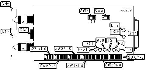
CONNECTIONS |
|||
Function |
Label |
Function |
Label |
| 25-pin data port | CN1 |
RG-58A/U connector - receive (BNC-T) | CN4 |
| RG-58A/U connector - transmit (BNC-T) | CN2 |
Power switch | SW8 |
| G.703 interface(RJ-45) | CN3 |
||
USER CONFIGURABLE SETTINGS |
|||
Setting |
Label |
Position |
|
| » | Factory configured - do not alter | SW2/1-8 |
Unidentified |
| » | Factory configured - do not alter | SW3/1-8 |
Unidentified |
| » | Factory configured - do not alter | SW4/1-8 |
Unidentified |
| » | Factory configured - do not alter | SW5/1-8 |
Unidentified |
| Normal receive clock polarity enabled | SW6/3 |
Off |
|
| Inverted receive clock polarity enabled | SW6/3 |
On |
|
| Normal transmit clock polarity enabled | SW6/4 |
Off |
|
| Inverted transmit clock polarity enabled | SW6/4 |
On |
|
| » | Factory configured - do not alter | SW6/5 |
Unidentified |
| » | Factory configured - do not alter | SW6/6 |
Unidentified |
| » | Factory configured - do not alter | SW6/7 |
Unidentified |
| Data port in DCE mode | SW6/8 |
Off |
|
| Data port in DTE mode | SW6/8 |
On |
|
E1 LINE IMPEDANCE |
|||||
Setting |
SW1/1 |
SW1/2 |
SW1/3 |
SW1/4 |
SW1/5 |
75 Ohm operation (CE approved) |
Off |
Off |
Off |
Off |
Off |
120 Ohm operation (CE approved) |
On |
On |
On |
On |
On |
75 Ohm operation (older models) |
On |
On |
Off |
Off |
Off |
120 Ohm operation (older models) |
Off |
Off |
On |
On |
On |
RX/TX TIMING |
|||
Receive Timing |
Transmit Timing |
SW6/1 |
SW6/2 |
Recover from E1 network port |
Source from data port |
Off |
Off |
Source from data port |
Source from data port |
Off |
On |
Recover from E1 network port |
Source from E1 network port |
On |
Off |
Established by internal oscillator |
Established by internal oscillator |
On |
On |
LOOPBACK TEST SELECTOR |
||
Function |
Label |
Position |
Recovery port loopback initiated |
SW7 |
1 |
Normal operation. Loopback not activated |
SW7 |
2 |
Data port loopback initiated |
SW7 |
3 |
DIAGNOSTIC LED(S) |
|||
LED |
Color |
Status |
Condition |
DTE |
Green |
On |
DTE mode enabled; power is on |
DTE |
Green |
Off |
Device not in DTE mode or power is off |
DCE |
Green |
On |
DCE mode enabled; power is on |
DCE |
Green |
Off |
Device not in DCE mode or power is off |
TD |
Yellow |
On |
Data is being transmitted from the data port (CN1) |
TD |
Yellow |
Off |
Data is not being transmitted from the data port (CN1) |
RD |
Yellow |
On |
Data is being received at the data port (CN1) |
RD |
Yellow |
Off |
Data is not being recieved at the data port (CN1) |
TST |
Red |
On |
Device is conducting a loopback test |
TST |
Red |
Off |
Device is not conducting a loopback test |
ALM |
Red |
On |
Alarm condition detected on network |
ALM |
Red |
Off |
Alarm condition not detected on network |
TXCL |
Red |
On |
Transmit clock loss detected |
TXCL |
Red |
Off |
Transmit clock loss not detected |
RXSL |
Red |
On |
Receive signal loss detected |
RXSL |
Red |
Off |
Receive signal loss not detected |