RAD DATA COMMUNICATIONS, INC.
SRM-8V
|
Card Type |
Modem (synchronous/asynchronous) |
|
Chipset |
Unidentified |
|
Maximum Data Rate |
38.4Kbps |
|
Data Bus |
Serial |
|
Data Modulation |
Unidentified |
|
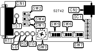
CONNECTIONS |
|||
|
Function |
Label |
Function |
Label |
|
V.24 serial port |
CN1 |
Line out via screw terminals (see pinout below) |
SC1 |
|
Line out |
CN2 |
||
|
SC1 PINOUT |
|||
|
Function |
Screw |
Function |
Screw |
|
Receive line |
1 |
Transmit line |
4 |
|
Receive line |
2 |
Transmit line |
5 |
|
Ground |
3 |
||
|
USER CONFIGURABLE SETTINGS |
|||
|
Setting |
Label |
Position |
|
| » |
Stop bit shortened by 12.5% in asynchronous mode |
SW6/1 |
Off |
|
Stop bit shortened by 25% in asynchronous mode |
SW6/1 |
On |
|
| » |
CD signal forced high |
SW6/4 |
On |
|
CD signal follows RTS |
SW6/4 |
Off |
|
| » |
Line type is 4-wire |
SW7/1 |
Off |
|
Line type is 2-wire |
SW7/1 |
On |
|
| » |
Pin 18 of CN1 has no function |
SW7/2 |
Off |
|
Pin 18 of CN1 begins local analog loopback test |
SW7/2 |
On |
|
| » |
Pin 21 of CN1 has no function |
SW7/3 |
Off |
|
Pin 21 of CN1 begins remote digital loopback test |
SW7/3 |
On |
|
| » |
LEDs enabled |
SW7/4 |
On |
|
LEDs disabled |
SW7/4 |
Off |
|
|
LINE SPEED SELECTION |
||
|
Setting |
SW3 |
|
|
2400bps |
Position 7 |
|
|
4800bps |
Position 6 |
|
|
7200bps |
Position 5 |
|
| » |
9600bps |
Position 4 |
|
14.4Kbps |
Position 3 |
|
|
19.2Kbps |
Position 2 |
|
|
38.4Kbps |
Position 0 |
|
|
RTS TO CTS DELAY SELECTION |
|||
|
Setting |
SW5/1 |
SW5/2 |
|
|
0 mS |
Off |
Off |
|
| » |
4 mS |
Off |
On |
|
34 mS |
On |
Off |
|
|
273 mS |
On |
On |
|
|
TRANSMIT CLOCK SOURCE SELECTION |
||||
|
Setting |
SW5/3 |
SW5/4 |
SW5/5 |
|
|
Asynchronous mode |
Off |
On |
Off |
|
|
Remote clock source |
Off |
Off |
On |
|
| » |
Internal clock source |
Off |
Off |
Off |
|
External clock source |
On |
Off |
Off |
|
|
CHARACTER LENGTH SELECTION |
|||
|
Setting |
SW6/2 |
SW6/3 |
|
|
8 bits |
Off |
Off |
|
|
9 bits |
Off |
On |
|
| » |
10 bits |
On |
Off |
|
11 bits |
On |
On |
|
|
DTE/DCE MODE SELECTION |
||
|
Setting |
SW1 |
SW2 |
|
DCE |
Off |
Off |
|
DTE |
On |
On |
|
TEST MODE SELECTION |
||
|
Setting |
SW4 |
|
|
Local analog loopback test mode |
Position 1 |
|
| » |
Normal operation |
Position 2 |
|
Remote digital loopback test mode |
Position 3 |
|
|
DIAGNOSTIC LED(S) |
|||
|
LED |
Color |
Status |
Condition |
|
TST |
Red |
On |
Modem is in test mode |
|
TST |
Red |
Off |
Modem is not in test mode |
|
CD |
Unidentified |
On |
Carrier signal detected |
|
CD |
Unidentified |
Off |
Carrier signal not detected |
|
RD |
Unidentified |
On |
Modem is receiving data |
|
RD |
Unidentified |
Off |
Modem is not receiving data |
|
TD |
Unidentified |
On |
Modem is transmitting data |
|
TD |
Unidentified |
Off |
Modem is not transmitting data |
|
RTS |
Unidentified |
On |
RTS signal is high |
|
RTS |
Unidentified |
Off |
RTS signal is low |