MOTOROLA, INC.
VANGUARD 100PC
| Card Type | Frame relay adapter |
| Processor | Motorola 68302 |
| Processor Speed | 15.36MHz |
| Chip Set | Unidentified |
| Maximum Onboard Memory | 2MB DRAM/1MB Flash RAM |
| I/O Options | Serial port |
| Data Bus | 16-bit ISA |
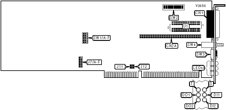
CONNECTIONS |
|||
Function |
Label |
Function |
Label |
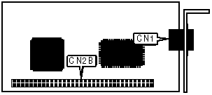
| V.11 V.24, V.35, V.36, or DSU port 2 | CN1 |
Reset button | SW4 |
| Daughterboard header for port 1 (on both front and back of card) | CN2A |
||
USER CONFIGURABLE SETTINGS |
|||
Setting |
Label |
Position |
|
| » | Port 2 pin 22 used for ring indicator | SW2/9 |
Off |
| Port 2 pin 22 used to enter test mode in DCE mode, ring indicator in DTE mode | SW2/9 |
On |
|
| » | Port 2 pin 25 used for test mode indicator | SW2/9 |
Off |
| Port 2 pin 25 used for test mode indicator for DCE mode, busy out for DTE mode | SW2/9 |
On |
|
| » | Use stored serial configuration | SW3/1 |
Off |
| Force serial configuration to 9600bps, no parity, 8 data bits, 1 stop bit | SW3/1 |
On |
|
| » | Factory diagnostic mode disabled | SW3/2 |
Off |
| Factory diagnostic mode enabled | SW3/2 |
On |
|
| » | Normal operation | SW3/3 |
Off |
| Reset entire configuration to factory defaults | SW3/3 |
On |
|
| » | Hardware configuration only | SW3/4 |
Off |
| Allow software to override SW3/1 through SW3/3 and SW4 | SW3/4 |
On |
|
| Note: To use SW3/3, power up the adapter, turn SW3/3 on, press the reset button, and turn SW3/3 back off again. | |||
COM PORT ADDRESS |
||
Setting |
J11 |
J12 |
2F8h (COM2:) |
Closed |
Closed |
3E8h (COM3:) |
Open |
Closed |
2E8h (COM4:) |
Closed |
Open |
1A8h |
Open |
Open |
| Note: This sets the address for the third serial port. It is accessed by a serial port on another card set at the same address. | ||
INTERRUPT |
||||||
Setting |
J7/A |
J7/B |
J7/C |
J7/D |
J7/E |
J7/F |
IRQ3 |
Open |
Open |
Open |
Open |
Open |
Closed |
IRQ4 |
Open |
Open |
Open |
Open |
Closed |
Open |
IRQ5 |
Open |
Open |
Open |
Closed |
Open |
Open |
IRQ10 |
Open |
Open |
Closed |
Open |
Open |
Open |
IRQ11 |
Open |
Closed |
Open |
Open |
Open |
Open |
IRQ15 |
Closed |
Open |
Open |
Open |
Open |
Open |
PLUG-N-PLAY MODE |
||||||
Setting |
SW1/A |
SW1/B |
SW1/C |
SW1/D |
SW1/E |
SW1/F |
Plug-N-Play |
Pins 1 & 2 |
Pins 1 & 2 |
Pins 1 & 2 |
Pins 1 & 2 |
Pins 1 & 2 |
Pins 1 & 2 |
Standard |
Pins 2 & 3 |
Pins 2 & 3 |
Pins 2 & 3 |
Pins 2 & 3 |
Pins 2 & 3 |
Pins 2 & 3 |
| Note: Pins designated are in the closed position. | ||||||
PORT 2 TYPE |
||||||
Setting |
SW2/1 |
SW2/2 |
SW2/3 |
SW2/4 |
SW2/5 |
SW2/6 |
V.11 DTE |
Off |
Off |
Off |
Off |
Off |
On |
V.11 DCE |
Off |
Off |
Off |
Off |
Off |
On |
V.24 DTE |
On |
On |
On |
On |
On |
Off |
V.24 DCE |
On |
On |
On |
On |
On |
Off |
V.35 DTE |
Off |
Off |
Off |
Off |
Off |
On |
V.35 DCE |
Off |
Off |
Off |
Off |
Off |
On |
V.36 DTE |
Off |
Off |
Off |
Off |
Off |
On |
V.36 DCE |
Off |
Off |
Off |
Off |
Off |
On |
DSU |
Off |
Off |
Off |
Off |
Off |
On |
PORT 2 TYPE (CON'T) |
|||
Setting |
SW2/7 |
SW2/8 |
U1 |
V.11 DTE |
On |
On |
V.11 module in position 1 |
V.11 DCE |
On |
On |
V.11 module in position 2 |
V.24 DTE |
Off |
Off |
V.24 module in position 1 |
V.24 DCE |
Off |
Off |
V.24 module in position 2 |
V.35 DTE |
On |
On |
V.35 module in position 1 |
V.35 DCE |
On |
On |
V.35 module in position 2 |
V.36 DTE |
On |
On |
V.36 module in position 1 |
V.36 DCE |
On |
On |
V.36 module in position 2 |
DSU |
On |
On |
DSU module in position 1 |
DIAGNOSTIC LED(S) (RESET AND POWER-UP) |
|||
T |
S |
Other LEDs |
Condition |
On |
On |
On |
Card is beginning self-test |
Blinking |
Off |
Off |
Card is performing self-test |
On |
On |
On |
Card is beginning to load software |
Off |
Slow blink |
Off |
Card is loading software into DRAM from flash RAM |
Off |
Off |
Off |
Card is initializing configuration |
On |
Off |
Off |
Self-test failed |
Off |
Fast blink |
Off |
Flash RAM contains invalid code |
| Note: On reset or power-up, the LEDs should go through, in order, the first five actions shown above. | |||
DIAGNOSTIC LED(S) (NORMAL OPERATION) |
|||
LED |
Color |
Status |
Condition |
T |
Unidentified |
On |
Test failed |
T |
Unidentified |
Off |
No test in progress or test passed |
T |
Unidentified |
Blinking |
Test in progress |
S |
Unidentified |
On |
Software is running |
S |
Unidentified |
Off |
Software not running |
S |
Unidentified |
Blinking |
Software is downloading or card is booting |
DO1 |
Unidentified |
On |
Card is transmitting MARK signal on port 1 |
DO1 |
Unidentified |
Off |
Card is transmitting SPACE signal on port 1 |
DI1 |
Unidentified |
On |
Card is receiving MARK signal on port 1 |
DI1 |
Unidentified |
Off |
Card is receiving SPACE signal on port 1 |
DO2 |
Unidentified |
On |
Card is transmitting MARK signal on port 2 |
DO2 |
Unidentified |
Off |
Card is transmitting SPACE signal on port 2 |
DI2 |
Unidentified |
On |
Card is receiving MARK signal on port 2 |
DI2 |
Unidentified |
Off |
Card is receiving SPACE signal on port 2 |
| Card Type | Serial |
| I/O Options | Serial port |
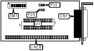
CONNECTIONS |
|||
Function |
Label |
Function |
Label |
| V.11 V.24, V.35, V.36, or DSU port | CN1 |
Header to main board (on both front and back of card) | CN2B |
USER CONFIGURABLE SETTINGS |
|||
Setting |
Label |
Position |
|
| » | Pin 22 used for ring indicator | P22 |
Pins 2 & 3 closed |
| Pin 22 used to enter test mode in DCE mode, ring indicator in DTE mode | P22 |
Pins 1 & 2 closed |
|
| » | Pin 25 used for test mode indicator | P25 |
Pins 1 & 2 closed |
| Pin 25 used for test mode indicator for DCE mode, busy out for DTE mode | P25 |
Pins 2 & 3 closed |
|
SERIAL PORT TYPE |
||||||
Setting |
SW1/1 |
SW1/2 |
SW1/3 |
SW1/4 |
SW1/5 |
SW1/6 |
V.11 DTE |
Off |
Off |
Off |
Off |
Off |
On |
V.11 DCE |
Off |
Off |
Off |
Off |
Off |
On |
V.24 DTE |
On |
On |
On |
On |
On |
Off |
V.24 DCE |
On |
On |
On |
On |
On |
Off |
V.35 DTE |
Off |
Off |
Off |
Off |
Off |
On |
V.35 DCE |
Off |
Off |
Off |
Off |
Off |
On |
V.36 DTE |
Off |
Off |
Off |
Off |
Off |
On |
V.36 DCE |
Off |
Off |
Off |
Off |
Off |
On |
DSU |
Off |
Off |
Off |
Off |
Off |
On |
SERIAL PORT TYPE (CON'T) |
|||
Setting |
SW1/7 |
SW1/8 |
U1 |
V.11 DTE |
On |
On |
V.11 module in position 1 |
V.11 DCE |
On |
On |
V.11 module in position 2 |
V.24 DTE |
Off |
Off |
V.24 module in position 1 |
V.24 DCE |
Off |
Off |
V.24 module in position 2 |
V.35 DTE |
On |
On |
V.35 module in position 1 |
V.35 DCE |
On |
On |
V.35 module in position 2 |
V.36 DTE |
On |
On |
V.36 module in position 1 |
V.36 DCE |
On |
On |
V.36 module in position 2 |
DSU |
On |
On |
DSU module in position 1 |
| Card Type | ISDN TA |
| ISDN Transfer Rate | 64Kbps x 2 |
| ISDN Protocol | Unidentified |
| Switch Type | Unidentified |
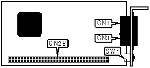
CONNECTIONS |
|||
Function |
Label |
Function |
Label |
| Line in/out | CN1 |
Line in/out | CN3 |
| Header to main board (on both front and back of card) | CN2B |
||
| Note: Two connectors are provided so the user can daisy-chain devices on the S/T bus. | |||
USER CONFIGURABLE SETTINGS |
|||
Setting |
Label |
Position |
|
| » | S/T bus not terminated | SW1 |
Off |
| S/T bus terminated | SW1 |
On |
|
| Card Type | ISDN TA |
| ISDN Transfer Rate | 64Kbps x 2 |
| ISDN Protocol | Unidentified |
| Switch Type | Unidentified |
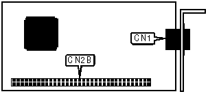
CONNECTIONS |
|||
Function |
Label |
Function |
Label |
| Line out | CN1 |
Header to main board (on both front and back of card) | CN2B |
VANGUARD 100PC (DSU DAUGHTERCARD)
| Card Type | DDS DSU |
| DSU Transfer Rate | 56Kbps |
| Modulation Protocol | Unidentified |
CONNECTIONS |
|||
Function |
Label |
Function |
Label |
| Line out | CN1 |
Header to main board (on both front and back of card) | CN2B |