DATAEXPERT CORPORATION
MGX7510
|
Device Type |
Mainboard |
|
Processor |
CX MediaGX |
|
Processor Speed |
120/133/150/166/180/200MHz |
|
Chip Set |
CX 5510 |
|
Video Chip Set |
Unidentified |
|
Audio Chip Set |
Unidentified |
|
Maximum Onboard Memory |
128MB (EDO and SDRAM supported) |
|
Cache |
16KB |
|
BIOS |
Unidentified |
|
Dimensions |
254mm x 218mm |
|
I/O Options |
32-bit PCI slots (3), floppy drive interface, game interface, green PC connector, IDE interfaces (2), parallel port, PS/2 mouse interface, serial ports (2), IR connector, ATX power connector, audio in - CD-ROMs (2) |
|
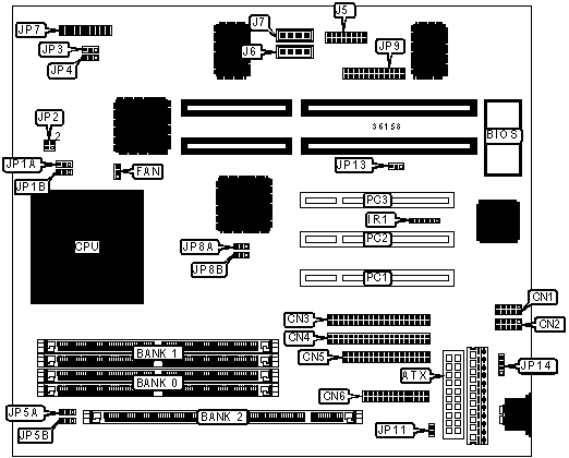
CONNECTIONS |
|||
|
Purpose |
Location |
Purpose |
Location |
|
ATX power connector |
ATX |
IR connector |
IR1 |
|
Serial port 2 |
CN1 |
Speaker |
JP7/pins 1/3/5/7 |
|
Serial port 1 |
CN2 |
Power LED |
JP7/pins 2/4/6 |
|
IDE interface 1 |
CN3 |
Reset switch |
JP7/pins 13 & 14 |
|
IDE interface 2 |
CN4 |
IDE interface LED |
JP7/pins 15 & 16 |
|
Floppy drive interface |
CN5 |
Green PC connector |
JP7/pins 17 & 18 |
|
Parallel port |
CN6 |
Green PC LED |
JP7/pins 19 & 20 |
|
CPU fan power |
FAN |
MIDI board connector |
JP9 |
|
Game interface |
J5 |
Soft off power supply |
JP11 |
|
Audio in - CD-ROM |
J6 |
PS/2 mouse interface |
JP14 |
|
Audio in - CD-ROM |
J7 |
32-bit PCI slots |
PC1 - PC3 |
|
USER CONFIGURABLE SETTINGS |
|||
|
Function |
Label |
Position |
|
|
» |
CMOS memory normal operation |
JP13 |
Pins 1 & 2 closed |
|
|
CMOS memory clear |
JP13 |
Pins 2 & 3 closed |
|
SIMM CONFIGURATION |
||
|
Size |
Bank 0 |
Bank 1 |
|
8MB |
(2) 1M x 36 |
None |
|
16MB |
(2) 2M x 36 |
None |
|
16MB |
(2) 1M x 36 |
(2) 1M x 36 |
|
24MB |
(2) 2M x 36 |
(2) 1M x 36 |
|
32MB |
(2) 4M x 36 |
None |
|
32MB |
(2) 2M x 36 |
(2) 2M x 36 |
|
40MB |
(2) 4M x 36 |
(2) 1M x 36 |
|
48MB |
(2) 4M x 36 |
(2) 2M x 36 |
|
64MB |
(2) 8M x 36 |
None |
|
64MB |
(2) 4M x 36 |
(2) 4M x 36 |
|
72MB |
(2) 8M x 36 |
(2) 1M x 36 |
|
80MB |
(2) 8M x 36 |
(2) 2M x 36 |
|
96MB |
(2) 8M x 36 |
(2) 4M x 36 |
|
128MB |
(2) 8M x 36 |
(2) 8M x 36 |
|
Note: Board accepts EDO memory. |
||
|
DIMM CONFIGURATION |
|
|
Size |
Bank 2 |
|
8MB |
(1) 1M x 64 |
|
16MB |
(1) 2M x 64 |
|
32MB |
(1) 4M x 64 |
|
64MB |
(1) 8M x 64 |
|
128MB |
(1) 16M x 64 |
|
Note: Board accepts EDO and SDRAM memory. |
|
|
DIMM VOLTAGE CONFIGURATION |
||
|
Voltage |
JP5A |
JP5B |
|
3.3v |
Pins 2 & 3 closed |
Pins 2 & 3 closed |
|
5v |
Pins 1 & 2 closed |
Pins 1 & 2 closed |
|
CPU SPEED SELECTION |
||||||
|
Speed |
Clock Speed |
Multiplier |
JP1A |
JP1B |
JP8A |
JP8B |
|
120MHz |
30MHz |
4x |
1 & 2 |
1 & 2 |
2 & 3 |
1 & 2 |
|
133MHz |
33MHz |
4x |
1 & 2 |
1 & 2 |
1 & 2 |
2 & 3 |
|
150MHz |
30MHz |
5x |
2 & 3 |
1 & 2 |
2 & 3 |
1 & 2 |
|
166MHz |
33MHz |
5x |
2 & 3 |
1 & 2 |
1 & 2 |
2 & 3 |
|
180MHz |
30MHz |
6x |
1 & 2 |
2 & 3 |
2 & 3 |
1 & 2 |
|
200MHz |
33MHz |
6x |
1 & 2 |
2 & 3 |
1 & 2 |
2 & 3 |
|
Note: Indicated pins are in the closed position. |
||||||
|
CPU VOLTAGE SELECTION (SINGLE) |
|||
|
Voltage |
JP2 |
JP3 |
JP4 |
|
2.9v |
Pins 1 & 2 closed |
Pins 2 & 3 closed |
Pins 2 & 3 closed |
|
3.6v |
Pins 3 & 4 closed |
Pins 2 & 3 closed |
Pins 2 & 3 closed |
|
CPU VOLTAGE SELECTION (DUAL) |
||||
|
V Core |
V I/O |
JP2 |
JP3 |
JP4 |
|
2.9v |
3.3v |
1 & 2 |
1 & 2 |
1 & 2 |
|
3.6v |
3.3v |
3 & 4 |
1 & 2 |
1 & 2 |
|
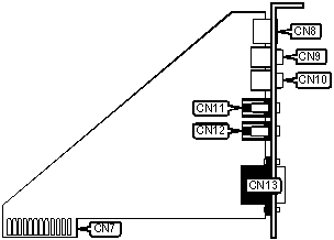
CONNECTIONS |
|||
|
Purpose |
Location |
Purpose |
Location |
|
MGX-midi connector |
CN7 |
Line in |
CN11 |
|
S-TRM connector |
CN8 |
Microphone in |
CN12 |
|
Video out |
CN9 |
VGA connector |
CN13 |
|
Line out |
CN10 |
32-bit PCI slots |
PC1 - PC3 |