SBE, INC.
VCOM-54
| Card Type | Misc I/O Card |
| Processor | Motorola |
| Processor Speed | 25MHz |
| Chip Set | Proprietary |
| I/O Options | 8 channel X.21 connectors, RJ-45 UTP connectors |
| Maximum Transmission Rate | 5Mbps |
| Maximum Onboard Memory | 4MB |
| Data Modulation Protocol | X.25 |
| Data Bus | VME bus |
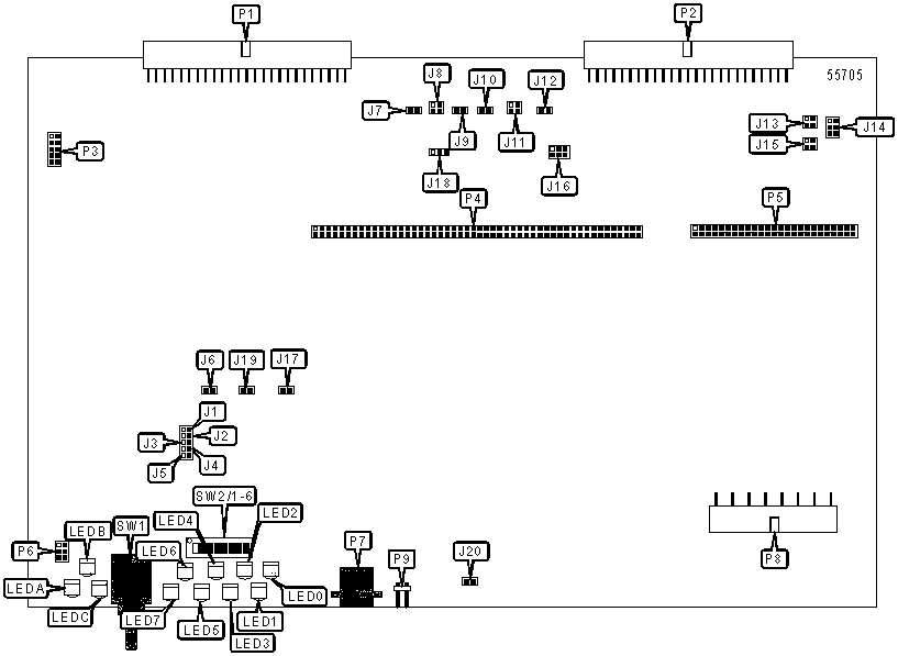
CONNECTIONS |
|||
Function |
Label |
Function |
Label |
| VME bus interface | P 1 |
JTAG | P6 |
| VME bus/Serial communications port | P2 | RJ-45 UTP connector | P7 |
| BDM | P3 | AUI connector | P8 |
| Mezzanine LIM 50-pin connector | P4 | Asynchronous serial port 1 | P9 |
| Mezzanine LIM 100-pin connector | P5 | Asynchronous serial port 2 | J16 |
USER CONFIGURABLE SETTINGS |
|||
Setting |
Label |
Position |
|
| Bank 0 bootup selected | J3 | Closed | |
| Bank 1 bootup selected | J3 | Open | |
| » | Factory configured - do not alter | J4 | Unidentified |
| » | Factory configured - do not alter | J5 | Unidentified |
| Manual reset also asserts SYSRESET on the VMEbus | J6 | Closed | |
| Manual reset does not assert SYSRESET on the VMEbus | J6 | Open | |
| TxC connection to RxC in Channel3 enabled | J7 | Closed | |
| TxC connection to RxC in Channel3 disabled | J7 | Open | |
| TxC connection to RxC in Channel5 enabled | J9 | Closed | |
| TxC connection to RxC in Channel5 disabled | J9 | Open | |
| TxC connection to RxC in Channel7 enabled | J10 | Closed | |
| TxC connection to RxC in Channel7 disabled | J10 | Open | |
| TxC connection to RxC in Channel1 enabled | J12 | Closed | |
| TxC connection to RxC in Channel1 disabled | J12 | Open | |
| Reset selected | SW1 | Reset | |
| Abort selected | SW1 | Abort | |
MEMORY SIZE AND TYPE |
|||
F unction |
J1 | J2 | |
| Flash: 128KB & 256KB (29F010) or 256KB & 512KB (29F020) | Closed | Closed | |
| Flash: 512KB or 1024KB (27F040) | Open | Closed | |
| EEPROM: 128KB & 256KB (27C010) or 256KB & 512KB (27C020) | Closed | Open | |
| EEPROM: 512KB or 1024KB (27C040) | Open | Open | |
BAUD RATE SOURCE SELECTION (CHANNEL 0) |
||
F unction |
J11 | |
| TxC to RxC connection enabled | Pins 1 & 3 closed | |
| Input to MC68360 PA pin for External BRG oscillator | Pins 2 & 4 closed | |
| Input to MC68360 PA pin for External BRG oscillator with TxC to RxC connection | Pins 1 & 3, 2 & 4 closed | |
| Input to MC68360 PA pin for external RxC | Pins 1 & 2 closed | |
BAUD RATE SOURCE SELECTION (CHANNEL 2) |
||
F unction |
J13 | |
| TxC to RxC connection enabled | Pins 1 & 3 closed | |
| Input to MC68360 PA pin for External BRG oscillator | Pins 2 & 4 closed | |
| Input to MC68360 PA pin for External BRG oscillator with TxC to RxC connection | Pins 1 & 3, 2 & 4 closed | |
| Input to MC68360 PA pin for external RxC | Pins 3 & 4 closed | |
BAUD RATE SOURCE SELECTION (CHANNEL 4) |
||
F unction |
J8 | |
| TxC to RxC connection enabled | Pins 1 & 3 closed | |
| Input to MC68360 PA pin for External BRG oscillator | Pins 2 & 4 closed | |
| Input to MC68360 PA pin for External BRG oscillator with TxC to RxC connection | Pins 1 & 3, 2 & 4 closed | |
| Input to MC68360 PA pin for external RxC | Pins 1 & 2 closed | |
BAUD RATE SOURCE SELECTION (CHANNEL 6) |
||
F unction |
J15 | |
| TxC to RxC connection enabled | Pins 1 & 3 closed | |
| Input to MC68360 PA pin for External BRG oscillator | Pins 2 & 4 closed | |
| Input to MC68360 PA pin for External BRG oscillator with TxC to RxC connection | Pins 1 & 3, 2 & 4 closed | |
| Input to MC68360 PA pin for external RxC | Pins 1 & 2 closed | |
BAUD RATE OSCILLATOR FREQUENCY SELECTION |
||
| MC68360 Setting | J14 | |
| Master 18.432MHz | Pins 1 & 3 closed | |
| Master 21.616MHz | Pins 3 & 5 closed | |
| Slave 18.432MHz | Pins 2 & 4 closed | |
| Slave 21.616MHz | Pins 4 & 6 closed | |
| Master 18.432MHz & Slave 18.432MHz | Pins 1 & 3, 2 & 4 closed | |
| Master 21.616MHz & Slave 18.432MHz | Pins 3 & 5, 4 & 6 closed | |
| Master 18.432MHz & Slave 21.616MHz | Pins 1 & 3, 2 & 4 closed | |
| Master 21.616MHz & Slave 21.616MHz | Pins 3 & 5, 4 & 6 closed | |
| Note: J8, J11, J13 and/or J15 must have pins 2 & 4 closed for J14 settings to take on the corresponding channel. | ||
ETHERNET CONFIGURATION |
|||
F unction |
J18 | J19 | |
| VCOM-54 powers external AUI transceiver | Pins 2 & 3 closed | Closed | |
| VCOM-54 does not powers external AUI transceiver | Pins 2 & 3 closed | Open | |
| 10BaseT & VCOM-54 does not power external AUI transceiver | Pins 1 & 2 closed | Open | |
DIAGNOSTIC LEDS |
|||
LED |
Color |
Status |
Condition |
| LED0 - LED7 | Y ellow |
N/A | User Programmable |
| LEDA | Green | On |
Power is on |
| LEDA | Green | O ff |
Power is off, or bus default detected |
| LEDB | Red | On | Watchdog timer has timed out |
| LEDB | Red | Off |
Normal operation |
| LEDB | Red | On | System is reset |
| LEDB | Red | Off | Normal operation |