BRAIN BOXES
AD1220 & AD1221 (VER 2.1)
|
Card Type |
Analog to digital timing converter |
|
Chip Set |
Unidentified |
|
Maximum Onboard Memory |
Unidentified |
|
Data Bus |
16-bit ISA |
|
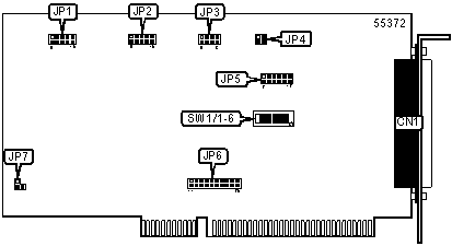
CONNECTIONS |
|
|
Function |
Label |
|
50-pin connector |
CN1 |
|
DAC1 OUTPUT RANGE SELECTION |
||
|
Range |
JP1 |
|
|
0 to +10V Unipolar |
Pins 2 & 7, 4 & 9, 5 & 10 closed |
|
|
O to +5V Unipolar |
Pins 2 & 7, 3 & 8, 5 & 10 closed |
|
|
-10 to +10V Bipolar |
Pins 1 & 6, 4 & 9 closed |
|
| » |
-5 to +5V Bipolar |
Pins 1 & 6, 4 & 9, 5 & 10 closed |
|
-2.5 to +2.5V Bipolar |
Pins 1 & 6, 3 & 8, 5 & 10 closed |
|
|
DAC0 OUTPUT RANGE SELECTION |
||
|
Range |
JP2 |
|
|
0 to +10V Unipolar |
Pins 2 & 7, 4 & 9, 5 & 10 closed |
|
|
O to +5V Unipolar |
Pins 2 & 7, 3 & 8, 5 & 10 closed |
|
|
-10 to +10V Bipolar |
Pins 1 & 6, 4 & 9 closed |
|
| » |
-5 to +5V Bipolar |
Pins 1 & 6, 4 & 9, 5 & 10 closed |
|
-2.5 to +2.5V Bipolar |
Pins 1 & 6, 3 & 8, 5 & 10 closed |
|
|
ADC INPUT RANGE SELECTION |
|||
|
Range |
JP3 |
JP4 |
|
|
0 to +10V Unipolar |
Pins 2 & 6, 4 & 8 closed |
Pins 1 & 2, 3 & 4 closed |
|
|
O to +5V Unipolar |
Pins 2 & 6, 4 & 8 closed |
Pins 2 & 4 closed |
|
|
0 to 2.5V Unipolar |
Pins 2 & 6, 4 & 8 closed |
Pins 1 & 3 closed |
|
|
0 to 1.25V Unipolar |
Pins 2 & 6, 4 & 8 closed |
Open |
|
|
-10 to +10V Bipolar |
Pins 1 & 5, 3 & 7 closed |
Pins 1 & 2, 3 & 4 closed |
|
| » |
-5 to +5V Bipolar |
Pins 1 & 5, 3 & 7 closed |
Pins 2 & 4 closed |
|
-2.5 to +2.5V Bipolar |
Pins 1 & 5, 3 & 7 closed |
Pins 1 & 3 closed |
|
|
-1.25 to +1.25V Bipolar |
Pins 1 & 5, 3 & 7 closed |
Open |
|
|
-0.625 to +0.625V Bipolar |
Pins 2 & 6, 3 & 7 closed |
Open |
|
|
ADC CHANNEL INPUT SELECTION |
||
|
Channel |
JP5 |
|
|
8 channel differential inputs |
Pins 1 & 7, 5 & 11 closed |
|
|
16 pseudo channel differential imputs |
Pins 2 & 8, 4 & 10, 6 & 12 closed |
|
| » |
16 channel single ended inputs |
Pins 2 & 8, 3 & 9, 6 & 12 closed |
|
SERIAL PORT 1 INTERRUPT SELECTION |
||
|
IRQ |
JP6 |
|
|
2 |
Pins 5 & 15 closed |
|
|
3 |
Pins 6 & 16 closed |
|
|
4 |
Pins 7 & 17 closed |
|
|
5 |
Pins 8 & 18 closed |
|
|
6 |
Pins 9 & 19 closed |
|
| » |
7 |
Pins 10 & 20 closed |
|
10 |
Pins 4 & 14 closed |
|
|
11 |
Pins 3 & 13 closed |
|
|
12 |
Pins 2 & 12 closed |
|
|
15 |
Pins 1 & 11 closed |
|
|
OUT0 CHANNEL SELECTION |
||
|
Channel |
JP7 |
|
| » |
Out0 not connected |
Pins 1 & 2 closed |
|
Out0 out via digital input 7, IDC pin 36 |
Pin 3 closed |
|
|
BASE I/O ADDRESS SELECTION |
|||||||
|
Setting |
SW1/1 |
SW1/2 |
SW1/3 |
SW1/4 |
SW1/5 |
SW1/6 |
|
|
0228h |
Off |
On |
Off |
On |
On |
On |
|
|
0220h |
On |
On |
Off |
On |
On |
On |
|
| » |
0218h |
Off |
Off |
On |
On |
On |
On |
|
0210h |
On |
Off |
On |
On |
On |
On |
|
|
0208h |
Off |
On |
On |
On |
On |
On |
|