INDUSTRIAL COMPUTER SOURCE
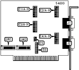
SPRT2A/AT
| Card Type | Serial card |
| I/O Options | serial ports (2) |
| Data Bus | 8-bit ISA |
CONNECTIONS |
|||
Function |
Label |
Function |
Label |
| 9-pin serial port | J1 |
9-pin serial port | J2 |
PORT/ENABLE DISABLE |
||
Function |
Label |
Position |
| Enables Port 1 | SW1/8 |
On |
| Disables Port 1 | SW1/8 |
Off |
| Enables Port 2 | SW2/8 |
On |
| Disables Port 2 | SW2/8 |
Off |
INTERFACE OPTIONS |
||||||||
Setting |
E1/A | E1/B | E1/C | E1/D | E1/E | E1/F | E1/G | E1/H |
| RS232 | 1 & 2 | 1 & 2 | 1 & 2 | 1 & 2 | 1 & 2 | 1 & 2 | 1 & 2 | 1 & 2 |
| RS422 | 2 & 3 | 2 & 3 | 2 & 3 | 2 & 3 | 2 & 3 | 1 & 2 | 1 & 2 | 1 & 2 |
| RS485 | 2 & 3 | Open | 2 & 3 | 2 & 3 | 2 & 3 | 2 & 3 | 2 & 3 | 2 & 3 |
| Note: Designated pins should be in the closed position. | ||||||||
INTERFACE OPTIONS |
||||||||
Setting |
E2/A | E2/B | E2/C | E2/D | E2/E | E2/F | E2/G | E2/H |
| RS232 | 1 & 2 | 1 & 2 | 1 & 2 | 1 & 2 | 1 & 2 | 1 & 2 | 1 & 2 | 1 & 2 |
| RS422 | 2 & 3 | 2 & 3 | 2 & 3 | 2 & 3 | 2 & 3 | 1 & 2 | 1 & 2 | 1 & 2 |
| RS485 | 2 & 3 | 2 & 3 | 2 & 3 | 2 & 3 | 2 & 3 | 2 & 3 | 2 & 3 | 2 & 3 |
| Note: Designated pins should be in the closed position. | ||||||||
INTERFACE OPTIONS |
||||||||
Setting |
E3/A | E3/B | E3/C | E3/D | E3/E | E3/F | E3/G | E3/H |
| RS232 | 1 & 2 | 1 & 2 | 1 & 2 | 1 & 2 | 1 & 2 | 1 & 2 | 1 & 2 | 1 & 2 |
| RS422 | 2 & 3 | 2 & 3 | 2 & 3 | 2 & 3 | 2 & 3 | 1 & 2 | 1 & 2 | 1 & 2 |
| RS485 | 2 & 3 | 2 & 3 | 2 & 3 | 2 & 3 | 2 & 3 | 2 & 3 | 2 & 3 | 2 & 3 |
| Note: Designated pins should be in the closed position. | ||||||||
INTERFACE OPTIONS |
||||||||
Setting |
E4/A | E4/B | E4/C | E4/D | E4/E | E4/F | E4/G | E4/H |
| RS232 | 1 & 2 | 1 & 2 | 1 & 2 | 1 & 2 | 1 & 2 | 1 & 2 | 1 & 2 | 1 & 2 |
| RS422 | 2 & 3 | 2 & 3 | 2 & 3 | 2 & 3 | 2 & 3 | 1 & 2 | 1 & 2 | 1 & 2 |
| RS485 | 2 & 3 | 2 & 3 | 2 & 3 | 2 & 3 | 2 & 3 | 2 & 3 | 2 & 3 | 2 & 3 |
| Note: Designated pins should be in the closed position. | ||||||||
INTERRUPT SELECTION |
|
Function |
E6 |
| Port 1: If COM1 is selected, setting must be for IRQ4 | Pins 5&6 closed |
| Port 1: If COM2 is selected, setting must be for IRQ3 | Pins 3&4 closed |
| Port 2: If COM1 is selected, setting must be for IRQ4 | Pins 13&14 closed |
| Port 2: If COM2 is selected, setting must be for IRQ3 | Pins 11&12 closed |
| Note: Both ports can have the same IRQ setting. | |
INTERRUPT MODE SELECTION |
|
Function |
E5 |
| Selects single interrupt mode for Port 1 | Pins 1&3 closed |
| Selects single interrupt mode for Port 2 | Pins 2&4 closed |
| Selects shared interrupt mode for Port 1 | Pins 3&5 closed |
| Selects shared interrupt mode for Port 2 | Pins 4&6 closed |
BASE I/O ADDRESS SELECTION: SW1 |
|||||||
Setting |
SW1/1 |
SW1/2 |
SW1/3 |
SW1/4 |
SW1/5 |
SW1/6 |
SW1/7 |
3F8h |
Off |
Off |
Off |
Off |
Off |
Off |
Off |
3F0h |
Off |
Off |
Off |
Off |
Off |
Off |
On |
3E0h |
Off |
Off |
Off |
Off |
Off |
On |
On |
380h |
Off |
Off |
Off |
On |
On |
On |
On |
300h |
Off |
Off |
On |
On |
On |
On |
On |
2D8h |
Off |
Off |
Off |
Off |
Off |
Off |
Off |
1F0h |
On |
Off |
Off |
Off |
Off |
Off |
On |
1E0h |
On |
Off |
Off |
Off |
Off |
On |
On |
1C0h |
On |
Off |
Off |
Off |
On |
On |
On |
180h |
On |
Off |
Off |
On |
On |
On |
On |
100h |
On |
Off |
On |
On |
On |
On |
On |
Note: A total of 255 base address settings are available. The switches are a binary representation of the decimal memory addresses. S1/1 is the Most Significant Bit and switch S1/7 is the Least Significant Bit. The switches have the following decimal values: S1/1=512, S1/2=256, S1/3=128, S1/4=64, S1/5=32, S1/6=16, S1/7=8. Turn off the switches and add the values of the switches to obtain the correct memory address. (Off=1, On=0) |
|||||||
BASE I/O ADDRESS SELECTION: SW2 |
|||||||
Setting |
SW2/1 |
SW2/2 |
SW2/3 |
SW2/4 |
SW2/5 |
SW2/6 |
SW2/7 |
3F8h |
Off |
Off |
Off |
Off |
Off |
Off |
Off |
3F0h |
Off |
Off |
Off |
Off |
Off |
Off |
On |
3E0h |
Off |
Off |
Off |
Off |
Off |
On |
On |
380h |
Off |
Off |
Off |
On |
On |
On |
On |
300h |
Off |
Off |
On |
On |
On |
On |
On |
2D8h |
Off |
Off |
Off |
Off |
Off |
Off |
Off |
1F0h |
On |
Off |
Off |
Off |
Off |
Off |
On |
1E0h |
On |
Off |
Off |
Off |
Off |
On |
On |
1C0h |
On |
Off |
Off |
Off |
On |
On |
On |
180h |
On |
Off |
Off |
On |
On |
On |
On |
100h |
On |
Off |
On |
On |
On |
On |
On |
Note: A total of 255 base address settings are available. The switches are a binary representation of the decimal memory addresses. S1/1 is the Most Significant Bit and switch S1/7 is the Least Significant Bit. The switches have the following decimal values: S1/1=512, S1/2=256, S1/3=128, S1/4=64, S1/5=32, S1/6=16, S1/7=8. Turn off the switches and add the values of the switches to obtain the correct memory address. (Off=1, On=0) |
|||||||