INFORTREND TECHNOLOGY, INC.
IFT-3102U2G
| Device Type | Hard drive controller |
| Processor | AM 5x86 |
| Processor Speed | 133MHz |
| Maximum Onboard Memory | 128MB DRAM |
| Drives Supported | Up to 75 SCSI devices |
| Floppy Drives Supported | None |
| Raid levels supported | 0,1,3,5 |
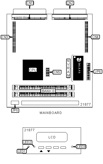
CONNECTIONS |
|||
Function |
Label |
Function |
Label |
| 160-pin connector to IFT-9178B4A backplane board | CN1 | 10-pin battery back-up daughterboard interface | CN5 |
| 160-pin connector to IFT-9178B4A backplane board | CN2 | Battery back-up daughterboard cable connector | JP5 |
| Daughterboard interface | CN3 | 20-pin battery back-up daughterboard interface | JP6 |
| Daughterboard interface | CN4 | ||
| Note: When JP6 is not being used by battery back-up daughterboard, it must be capped with included socket plug. Pin 1 of socket plug must line up with pin 1 on JP6. | |||
SIMM CONFIGURATION |
|
Size |
Bank 0 |
8MB |
(2) 1M x 32 |
16MB |
(2) 2M x 32 |
32MB |
(2) 4M x 32 |
64MB |
(2) 8M x 32 |
128MB |
(2) 16M x 32 |
| Note: EDO memory is recommended. | |
DIAGNOSTIC LED(S) |
|||
LED |
Color |
Status |
Condition |
| LED1 | Unidentified | On | Fault condition - a drive has failed |
| LED1 | Unidentified | Off | All drives operational |
| LED2 | Unidentified |
On |
Unprocessed cached data is still in memory |
| LED2 | Unidentified | Blinking | Data is being accessed |
| LED2 | Unidentified | Off | No activity |
| LED3 | Unidentified |
On |
Power is on |
| LED3 | Unidentified |
Off |
Power is off |
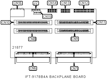
CONNECTIONS |
|||
Function |
Label |
Function |
Label |
| 160-pin connector to mainboard | CN6 | 26-pin Fault-bus interface | CN12 |
| 160-pin connector to mainboard | CN7 | RS-232C serial interface (COM 1) | CN13 |
| 68-pin Ultra2 Wide SCSI channel 0 connector | CN8 | 10-pin Redundant controller interface | CN14 |
| 68-pin Ultra2 Wide SCSI channel 3 connector | CN9 | I2C connector | CN15 |
| 68-pin Ultra2 Wide SCSI channel 1 connector | CN10 | Power connector | CN16 |
| 68-pin Ultra2 Wide SCSI channel 2 connector | CN11 | 5-pin battery pack cable connector | J2 |
| Note: The controller can be configured using VT-100 terminal emutation. The 10-pin RS-232 serial interface (CN13) can be converted to a 9-pin D-Sub male connector with the interface cable provided. | |||
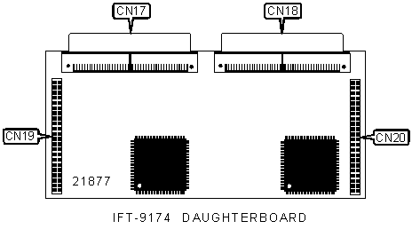
CONNECTIONS |
|||
Function |
Label |
Function |
Label |
| 160-pin connector to IFT-9178B4B backplane board | CN17 | Mainboard interface | CN19 |
| 160-pin connector to IFT-9178B4B backplane board | CN18 | Mainboard interface | CN20 |
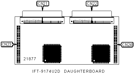
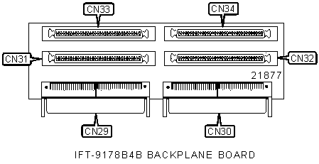
CONNECTIONS |
|||
Function |
Label |
Function |
Label |
| 160-pin connector to IFT-9178B4U2D backplane board | CN21 | Mainboard interface | CN23 |
| 160-pin connector to IFT-9178B4U2D backplane board | CN22 | Mainboard interface | CN24 |
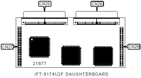
CONNECTIONS |
|||
Function |
Label |
Function |
Label |
| 160-pin connector to IFT-9178B4U2F backplane board | CN25 | Mainboard interface | CN27 |
| 160-pin connector to IFT-9178B4U2F backplane board | CN26 | Mainboard interface | CN28 |
CONNECTIONS |
|||
Function |
Label |
Function |
Label |
| 160-pin connector to IFT-9174 daughterboard | CN29 | 68-pin Ultra2 Wide SCSI channel 7 connector | CN32 |
| 160-pin connector to IFT-9174 daughterboard | CN30 | 68-pin Ultra2 Wide SCSI channel 5 connector | CN33 |
| 68-pin Ultra2 Wide SCSI channel 4 connector | CN31 | 68-pin Ultra2 Wide SCSI channel 6 connector | CN34 |
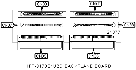
CONNECTIONS |
|||
Function |
Label |
Function |
Label |
| 160-pin connector to IFT-9174U2D daughterboard | CN35 | 68-pin SCSI channel 7 connector | CN38 |
| 160-pin connector to IFT-9174U2D daughterboard | CN36 | 68-pin SCSI channel 5 connector | CN39 |
| 68-pin SCSI channel 4 connector | CN37 | 68-pin SCSI channel 6 connector | CN40 |
| Note: Board contains (2) Ultra2 Wide SCSI connectors and (2) Ultra Wide differential SCSC connectors. | |||
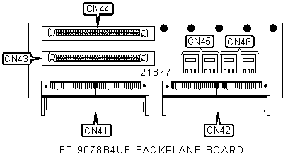
CONNECTIONS |
|||
Function |
Label |
Function |
Label |
| 160-pin connector to IFT-9064UF daughterboard | CN41 | 68-pin SCSI channel 5 connector | CN44 |
| 160-pin connector to IFT-9064UF daughterboard | CN42 | Fibre channel channel 6 connector | CN45 |
| 68-pin SCSI channel 4 connector | CN43 | Fibre channel channel 7 connector | CN46 |
| Note: Fibre channels can function either as 1 dual-loop or 2 single-loop channels. | |||
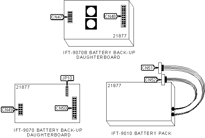
CONNECTIONS |
|||
Function |
Label |
Function |
Label |
| 10-pin mainboard interface | CN47 | 5-pin battery pack cable connector (long) | CN51 |
| 20-pin mainboard interface | CN48 | 5-pin battery pack cable connector for cascading (short) | CN52 |
| 10-pin mainboard interface | CN49 | 5-pin connector to IFT-9010 battery pack | JP10 |
| 20-pin mainboard interface | CN50 | ||
| Note: CN47 &
CN49 connect to CN5 on the mainboard. Note: CN48 & CN50 connect to JP6 on the mainboard. Note: Battery pack cable connector CN51 connects to J2 on the IFT-9178B4A backplane board or, if space permits, directly to JP10 on the IFT-9070 battery back-up daughterboard. Note: IFT-9070 & IFT-9010 are used together. IFT9070B does not require the battery pack due to onboard cells. |
|||
MISCELLANEOUS TECHNICAL NOTES |
Diagram not available for
IFT-9064UF daughterboard (connects to 9078B4UF backplane board). |